For Service Technician Use Only
DIAGNOSTICS (Cont.)
Low Profile Microwave Hood Combination
n
2-5
Display
Likely Failure
Condition
Recommended Repair Procedure
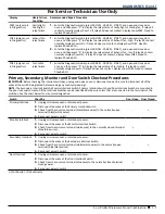
F9E3 (only occurs
in Diagnostics)
Cavity light /
Cooling fan
relay failure
1.
Enter the Diagnostics mode (press CANCEL - CANCEL - START), and open and close door
once, and then press “2” to display the relay status of cavity light or cooling fan. If relay K4
contact normally display show CL; If relay K4 does not contact, display show F9E3. Need to
replace Phoebe ACU.
FDE3 (only occurs
in Diagnostics)
Exhaust fan
relay failure
1.
Enter the Diagnostics mode (press CANCEL - CANCEL - START), and open and close door
once, and then press “4” to display the relay status of Exhaust fan - high. If relay K4 contact
normally display show HF H; if relay K4 does not contact, display show FDE3. Need to
replace Phoebe ACU.
2.
Enter the Diagnostics mode (press CANCEL - CANCEL - START), and open and close door
once, and then press “5” to display the relay status of Exhaust fan - low. If relay K5 contact
normally display show HF L; If relay K5 does not contact, display show FDE3. Need to
replace Phoebe ACU.
FDE2 (only occurs
in Diagnostics)
Turn table
relay failure
1.
Enter the Diagnostics mode (press CANCEL - CANCEL - START), and open and close door
once, and then press “3” to display the relay status of turn table. If relay K6 contact
normally display show tt; If relay K5 does not contact, display show FDE2. Need to replace
Phoebe ACU.
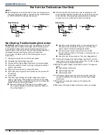
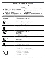
Primary, Secondary, Monitor and Door Switch Checkout Procedures
IMPORTANT:
Before checking the interlock switches, unplug microwave oven or disconnect power. Be sure to disconnect all of the
wires at the switch being tested before making any continuity readings.
NOTE:
The Secondary Interlock Switch, Monitor Interlock Switch, Primary Interlock Switch and Door Interlock Switch are mounted in
the door lock switch cradle. All the Interlock Switches can be identified by the wire colors that are connected to the terminals of the
switches. See the chart below for wire color designation.
Switch
Check By
Door Open Door Closed
Primary Interlock
1.
Unplug microwave oven or disconnect power.
2.
Disconnect the wires at the Primary Interlock Switch.
3.
Check from the common terminal (black/black wires) to the normally open
terminal (black/white wires).
4.
Reconnect wires to switch.
-
+
Monitor Interlock
1.
Unplug microwave oven or disconnect power.
2.
Disconnect the wires at the Monitor Interlock Switch.
3.
Check from the common terminal (white wire) to the normally closed terminal
(blue/blue wires).
4.
Reconnect wires to switch.
+
-
Secondary Interlock
1.
Unplug microwave oven or disconnect power.
2.
Disconnect the wires at the Secondary Interlock Switch.
3.
Check from the common terminal (white/white wires) to the normally open
terminal (blue/black wires).
4.
Reconnect wires to switch.
-
+
Door Interlock
1.
Unplug microwave oven or disconnect power.
2.
Disconnect the wires at the Door Interlock Switch.
3.
Check from the common terminal (blue wire) to the normally closed terminal
(orange wire).
4.
Reconnect wires to switch.
+
-
(+) Continuity (-) No Continuity


