background image

10

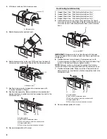
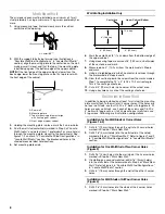
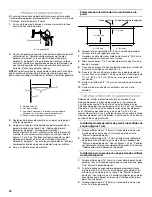
5. Cut the 1

¹⁄₂

" (3.8 cm) diameter hole at the circular shaded area 

“G” on the template. This hole is for the power supply cord.

NOTE: If upper cabinet is metal, the supply cord bushing needs to 
be installed around the supply cord hole, as shown.

6. Drill 3/8" (10 mm) holes at points “D” and “E” on the template. 

These are for two 1/4-20 x 3" round-head bolts and washers 
used to secure the microwave oven to the upper cabinet.

For Roof Venting Installation Only

7. Cut 3/4" (19 mm) hole at one corner of the shaded rectangular 

area “F” on Upper Cabinet Template.

8. Using a keyhole saw, cut out the rectangular area.

Install Damper Assembly

(for wall venting only)

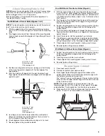
1. Check that damper blade moves freely, and opens toward the 

wall fully.

2. Push damper assembly through opening in mounting plate so 

that tabs in damper assembly lock damper assembly against 
mounting plate. Long tab of damper assembly must be to left 
side of mounting plate.

Install the Microwave Oven

IMPORTANT: The control side of the unit is the heavy side. 
Handle the microwave oven gently.
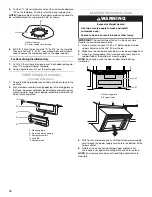
1. Place a washer on each 1/4-20 x 3" bolt and place inside 

upper cabinet near the 3/8" (10 mm) holes.

2. Make sure the microwave oven door is closed and taped shut.
3. Using 2 or more people, lift microwave oven and hang it on 

support tabs at the bottom of mounting plate.

NOTE: Do not grip or use the door or door handle during 
installation.

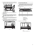
4. With front of microwave oven still tilted, thread power supply 

cord through the power supply cord hole in the bottom of the 
upper cabinet.

5. Rotate microwave oven up toward upper cabinet. Push 

microwave oven against mounting plate and hold in place.

NOTE: If microwave oven does not need to be adjusted, skip 
steps 6-8.

A. Metal cabinet
B. Power supply cord bushing

A. Mounting plate
B. Mounting plate opening

C. Damper assembly
D. Long tab

E. Damper blade

A

B

A

B

C

D

E

A. Mounting plate
B. Support tabs

WARNING

Excessive Weight Hazard

Use two or more people to move and install 
microwave oven.

Failure to do so can result in back or other injury.

A

B

Summary of Contents for MH1150XMB

Page 1: ...oles in Rear Wall 8 Attach Mounting Plate to Wall 9 Prepare Upper Cabinet 9 Install Damper Assembly 10 Install the Microwave Oven 10 Complete Installation 12 ASSISTANCE 12 Replacement Parts 12 Accessories 12 SEGURIDAD DE LA COMBINACIÓN MICROONDAS CAMPANA 13 ESPECIFICACIONES PARA EL DISEÑO DE LA VENTILACIÓN 13 REQUISITOS DE INSTALACIÓN 15 Piezas y herramientas 15 Requisitos de ubicación 15 Dimensio...

Page 2: ... performance If venting through the wall be sure that there is proper clearance within the wall for the damper to open fully If venting through the roof and rectangular to round transition is used be sure there is at least 3 7 6 cm of clearance between the top of the microwave oven and the transition piece See Rectangular to Round Transition illustration You can be killed or seriously injured if y...

Page 3: ...REMENTS Tools and Parts Tools Needed Gather the required tools and parts before starting installation Read and follow the instructions provided with any tools listed here A Roof cap B 6 15 2 cm min diameter round vent C Elbow for wall venting only D Wall cap E 3 x 10 to 6 8 3 x 25 4 cm to 15 2 cm rectangular to round transition piece F Vent extension piece at least 3 7 6 cm high A Rectangular to r...

Page 4: ...ven for cooking Check with your builder or cabinet supplier to make sure that the materials used will not discolor delaminate or sustain other damages Special Requirements For Wall Venting Installation Only The 12 x 4 30 5 x 10 2 cm cutout area must align with the rectangular hole in the mounting plate Cutout must be free of any obstructions so that the vent tube fits properly and the damper blade...

Page 5: ...ching damper plate to top of microwave oven exterior Slide damper plate back and lift up 2 Keep damper plate and screw together and set aside 3 Remove two screws attaching blower motor to back of microwave oven A Screws Electrical Shock Hazard Plug into a grounded 3 prong outlet Do not remove ground prong Do not use an adapter Do not use an extension cord Failure to follow these instructions can r...

Page 6: ...lower motor face back of microwave oven Lower blower motor back into microwave oven A Exhaust port IMPORTANT If blower motor is not positioned with flat sides facing the back of the microwave oven as shown performance will be poor 6 Reattach blower motor to back of microwave oven with 2 screws removed in Step 3 of Wall Venting Installation Only earlier in this section Securely tighten screws NOTE ...

Page 7: ...s show examples of preferred installation configurations with the mounting plate No Wall Studs at Corner Holes Figure 1 No Wall Studs at Corner Holes Figure 2 NOTE If wall stud is behind vent opening only ventless recirculating or roof venting installation can be done One Wall Stud at Two Corner Holes Figure 3 Wall Studs at All Four Corner Holes Figure 4 A Corner holes on mounting plate B Cabinet ...

Page 8: ...o complete the 12 x 4 30 5 x 10 2 cm rectangle This is the venting cutout area 11 Cut a 3 4 19 mm hole in one corner of the cutout area 12 Using a keyhole saw cut out the venting cutout area Drill Holes in Rear Wall In addition to being installed on at least 1 wall stud the mounting plate must attach to the wall at all 4 corner holes If the holes are not over wall studs use four 1 4 20 x 3 bolts w...

Page 9: ...le nut to go through the wall and to open 3 Position mounting plate on the wall making sure that the top of the mounting plate is aligned with the front edge of the upper cabinet 4 Push the 2 bolts with toggle nuts through the drywall and finger tighten the bolts to make sure toggle nuts have opened against drywall 5 Insert 2 lag screws into the remaining 2 corner holes 6 If installing on a second...

Page 10: ...ing plate Install the Microwave Oven IMPORTANT The control side of the unit is the heavy side Handle the microwave oven gently 1 Place a washer on each 1 4 20 x 3 bolt and place inside upper cabinet near the 3 8 10 mm holes 2 Make sure the microwave oven door is closed and taped shut 3 Using 2 or more people lift microwave oven and hang it on support tabs at the bottom of mounting plate NOTE Do no...

Page 11: ...orter bolts are available at most hardware stores Overtightening bolts may warp the top of the microwave oven To avoid warping wood filler blocks may be added The blocks must be the same thickness as the space between the upper cabinet bottom and the microwave oven A Bolts For Roof Venting Installation Only 1 Insert damper assembly through the cabinet cutout so that the long tab of the damper asse...

Page 12: ...behind the microwave oven door on the front frame of the microwave oven If you need additional assistance call us at our toll free number listed in the Use and Care Guide or visit us on the Web Replacement Parts If any of the installation hardware needs to be replaced call us at our toll free number listed in the Use and Care Guide and reference the appropriate part number listed here Accessories ...

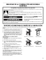
Page 13: ...alar 2 codos juntos Si va a tener la ventilación a través de la pared cerciórese de que haya el espacio adecuado dentro de la pared para poder abrir completamente la compuerta Si va a tener la ventilación a través del techo y va a usar un tubo de ajuste rectangular a redondo cerciórese de que haya un espacio de por lo menos 3 7 6 cm entre la parte superior del horno de microondas y el tubo de ajus...

Page 14: ...ión de 6 15 2 cm 73 pies 22 2 m en total Si el ducto de escape existente es redondo deberá usarse un tubo de ajuste rectangular a redondo También deberá instalarse un ducto de escape de extensión rectangular de 3 7 6 cm entre el ensamblaje de la compuerta y el tubo de ajuste rectangular a redondo para evitar que la compuerta se adhiera A Cubierta del techo B Ducto de escape redondo con diámetro mí...

Page 15: ...ndas durante la cocción Verifique con el constructor o distribuidor de gabinetes para asegurarse de que los materiales que se usen no se descoloren astillen ni sufran ningún otro tipo de daño Requisitos especiales Solamente para la instalación con ventilación en la pared El área del recorte de 12 x 4 30 5 x 10 2 cm deberá alinearse con el orificio rectangular en la placa de montaje El recorte debe...

Page 16: ...n No seguir estas instrucciones puede ocasionar la muerte incendio o choque eléctrico INSTRUCCIONES PARA LA CONEXIÓN A TIERRA GUARDE ESTAS INSTRUCCIONES Para todos los aparatos electrodomésticos de conexión con cable El horno de microondas debe estar conectado a tierra En caso de que se produzca un corto circuito la conexión a tierra reduce el riesgo de electrocución por medio de un alambre de esc...

Page 17: ...ar el método de ventilación o si va a volver a instalar el horno de microondas en otro lugar en donde pueda usar la ventilación a través de la pared o del techo Solamente para la instalación con ventilación en la pared 1 Saque el tornillo que sujeta la placa de la compuerta de tiro a la parte superior del exterior del horno de microondas Deslice hacia atrás la placa de la compuerta de tiro y leván...

Page 18: ...rte posterior del horno de microondas tal como se muestra éste tendrá un rendimiento insuficiente 6 Vuelva a sujetar el motor del soplador a la parte posterior del horno de microondas con los 2 tornillos que quitó en el paso 3 de Solamente para la instalación con ventilación en la pared anteriormente en esta sección Apriete firmemente los tornillos NOTA Si no se orienta el motor del soplador como ...

Page 19: ... preferidas con la placa de montaje Sin pies derechos de pared en los orificios de esquina Figura 1 Sin pies derechos de pared en los orificios de esquina Figura 2 NOTA Si el pie derecho de pared está detrás de la abertura del ducto de escape solamente se podrá hacer una instalación sin ducto de escape con recirculación o una instalación con ventilación en el techo Un pie derecho de pared en dos o...

Page 20: ...aso 7 hasta completar el rectángulo de 12 x 4 30 5 x 10 2 cm Ésta es el área de recorte de la ventilación 11 Corte un orificio de 3 4 19 mm en una esquina del área de corte 12 Corte el área de corte de la ventilación con una sierra caladora Taladrar orificios en la pared posterior Además de instalar la placa de montaje en al menos 1 pie derecho de pared la placa debe sujetarse a la pared en los 4 ...

Page 21: ...l paso 2 de Instalación sin pies derechos de pared en los orificios de esquina en la sección Taladrar orificios en la pared posterior 6 Controle la alineación de la placa de montaje asegurándose de que esté nivelada 7 Ajuste bien todos los tirafondos y pernos Un pie derecho de pared en dos orificios de esquina figura 3 1 Con las lengüetas de soporte de la placa de montaje mirando hacia adelante in...

Page 22: ...o se muestra 6 Taladre orificios de 3 8 10 mm en los puntos D y E de la plantilla Estos son para los dos pernos de cabeza redonda de 1 4 20 x 3 y las arandelas usadas para asegurar el horno de microondas al gabinete superior Solamente para la instalación con ventilación en el techo 7 Corte un orificio de 3 4 19 mm en una esquina del área F rectangular sombreada en la plantilla superior del gabinet...

Page 23: ...perior y dentro del horno de microondas Ajuste los pernos hasta que no exista ningún espacio entre el gabinete superior y el horno de microondas NOTAS Algunos gabinetes superiores pueden necesitar pernos más largos o más cortos que 3 7 6 cm Los pernos más largos o más cortos están disponibles en la mayoría de las ferreterías El apretar los pernos en exceso puede deformar la parte superior del horn...

Page 24: ...no Si necesita asistencia adicional llámenos a nuestro número gratuito que se indica en el Manual de uso y cuidado o visite nuestro sitio web Refacciones Si necesita reemplazar alguna pieza de ferretería de la instalación llámenos al número gratis que aparece en el Manual de uso y cuidado y tome como referencia el número de pieza apropiado que se enlista aquí Accesorios Los juegos de paneles de re...

Reviews: