background image

14

INSTALLATION SERVICE

Before installation

1. Please read this manual carefully before

installation.

2. The appliance must be installed according to

national wiring rules and according to this
manual by qualified technicians.

3. Any change of installation position must be

handled by professionals;

4. Check the product to verify that it has not been

damaged before installation.

5. Mount with the lowest moving parts of indoor

unit at least 2.0m above floor or grade Level.

6. After installing, the consumer must operate the

appliance correctly according to this manual,
keep a suitable storage for maintenance and
move of it in the future.

SAFETY PRECAUTION

1. The power supply must be of rated voltage

with special circuitry for the appliance. The
normal operating range of voltage is
90%~110% of  rated voltage. The diameter of
the power cord must comply with
requirements.

2. The user power supply shall have a reliable

grounding terminal. It is prohibited to connect
the grounding wire to the following items: 1)
Water Supply Pipe 2) Gas Pipe 3) Sewage Pipe
4) Other positions that are considered unsafe

3. Ensure safe grounding and a grounding wire

connected with the special grounding system of
the building, installed by professionals. The
appliance must be fitted with electrical leakage
protection switch and an air switch with
sufficient capacity (Refer to the following
chart). The air switch must also have a
magnetic and a thermal tripping function to
ensure protection in case of short-circuit and
overload.

4. Make sure that the power supply cord is long

enough to allow the right connection. Do not
use any extension cord for power supply.

5. If the supply cord is damaged, it must be

replaced by the manufacturer or its service
agent or a similarly qualified person in order to
avoid a hazard;

6. An all-pole disconnection switch having a

contact separation of at least 3mm in all poles
should be connected in fixed wiring.

7. Risk of electric shock can cause injury or death:

Disconnect all electric power supplies before
servicing.

8. The connection of power cord and the cable

connection between indoor unit and outdoor
unit shall be in accordance with the wiring
diagram attached on the appliance.

9. Once installation is completed, the electric

components must not be accessible to the
users.

10. Use two or more people to move and install

the appliance to avoid excessive weight hazard.

11. After unpacking the air conditioner, keep all

packaging materials well out of the reach of
children.

12. According to the character of refrigerant

(R410a), the pressure of the tube is very high,
so be sure to careful when you install and
repair the appliance.

Type

Model

Required Capacity of air
break switch 

Inverter

9k

16A

12k

16A

18k

16A

24k

32A

Summary of Contents for SIA120CO

Page 1: ...SPLIT TYPE WALL MOUNTED INVERTER AIR CONDITIONER USER S MANUAL AND INSTALLATION MANUAL MODELS SIA90IN SIA90CO SIA120IN SIA120CO SIA180IN SIA180CO SIA240IN SIA240CO ...

Page 2: ...irect exposure to cool air might be harmful to health It is advisable to set the louvers in order to avoid direct cool air and deflect it within the room Upon malfunctioning first turn the appliance off by pressing the power button on the remote control then disconnect it from power supply Do not switch the appliance on and off too often as this can damage the appliance Do not place any objects on...

Page 3: ...or unit 1 Air Intake 2 Front Panel 3 Display panel 4 Air Outlet 5 Electrical box 6 Emergency control button 7 Vertical Adjustment Louver Inside 8 Horizontal Adjustment Louver 9 Air Filter 10 Remote Control Outdoor unit 11 Air Intake 12 Pipes and Power Connection Cord 13 Drain Hose Note Condensate water drains at COOLING or DRY operation 14 Air Outlet ...

Page 4: ...oom temperature Operating mode indicator 2 Display blue lignt under COOL or DRY operation Display purple under FAN ONLY operation Default temperature showing is room temperature It shows set temperature under the settings by using remote controller then back to show room temperature after a few seconds ...

Page 5: ...ries or different types of batteries as this may cause the remote control to malfunction If you do not expect to use the remote control for some time take the batteries out to prevent leakage of battery acid in the remote control Operate the remote control within effective range Keep the remote control at least 1 meter from any TV set or HI FI equipment If the remote control does not work normally...

Page 6: ...w direction 8 SLEEP BUTTON Used to start or cancel Sleep mode operation 9 ACCURATE BUTTON Used to set the temperature at decimal digits 10 DRY BUTTON Used to start the dehumidifying operation Used to start or cancel the fan operation 12 TURBO BUTTON Used to start or cancel the fast cooling operation 15 HOUR BUTTON Used to set the hour of time 13 CLOCK BUTTON Used to set the time of clock 14 TIMER ...

Page 7: ...cator 6th Sense operation indicator Cooling operation indicator Dry operation indicator Fan operation indicator Timer on function indicator Timer off function indicator Sleep operation indicator Button lock indicator Display room temperature or set temperature Display the set time of Timer on and or Timer off display real time clock 6 Timer on and Timer off function indicator ...

Page 8: ...occur If that happens turn off the unit first and cut off the power supply then restore power supply again B It is better not to let the horizontal adjustment louver tilt downward for a long time at COOLING or DRY mode to prevent condensed water from dripping control rod of vertical adjustment louvers 5 Airflow direction control Horizontal airflow is automatically adjusted to a certain angle in ac...

Page 9: ...emperature will be rised by 1 C per hour till up to 28 C TURBO mode 5 Press the TURBO button to start or stop fast cooling COOL mode 2 Press the COOL button to start the cooling operation You can set the desired temperature fan speed and DRY mode 3 FAN ONLY mode 6 Press the FAN ONLY button to start or stop fan louver direction by pressing interrelated buttons See Press the DRY button to start the ...

Page 10: ...on function to let the appliance switch on at your desired time then you can enjoy the comfortable room temperature at the time you get home You can also set timer off function to enjoy a good sleep at night 1 Press the CLOCK button for one time the clock starts to flicker 2 Press the HOUR button to set the hour of time Time setting will be changed for 1 hour by each press 3 Press the MIN button t...

Page 11: ...Do not place any obstacles in front of the air outlet of the outdoor unit lest it increases the noise level Features of protection device Wait at least 3 minutes before restarting the unit after operation stops or changing mode during operation After connecting to power supply and turning on the appliance immediately a delay of 20 seconds may occur before it starts to operate If all operation has ...

Page 12: ...r unit Dangerous Electric shock Clean Air filter It is necessary to clean the air filter after using it for about 100 hours Clean the air filter every two weeks if the air conditioner operates in an extremely dusty environment 1 Disconnect from the power supply Turn off the appliance first before disconnecting from power supply 2 Take out air filter Fig C 1 Open the front panel 2 Press the handle ...

Page 13: ...on Peculiar smell This smell may come from another source such as furniture cigarette etc which is sucked in the unit and blown out with the air A sound of running water Normal behaviour caused by the flow of refrigerant in the air conditioner Cracking sound The sound may be generated by the expansion or contraction of the front panel due to temperature changes Mist sprays from the outlet Mist is ...

Page 14: ...he national wiring standards by authorized service people only Distance from wall should be over 50mm Distance from ceiling should be over 150mm Distance from floor should be over 2000mm Distance from the wall should be over 50mm Air intake distance from the wall should be over 250mm Air intake distance from the wall should be over 250mm Air outlet distance from the wall should be over 500mm Over ...

Page 15: ...ectrical leakage protection switch and an air switch with sufficient capacity Refer to the following chart The air switch must also have a magnetic and a thermal tripping function to ensure protection in case of short circuit and overload 4 Make sure that the power supply cord is long enough to allow the right connection Do not use any extension cord for power supply 5 If the supply cord is damage...

Page 16: ...it where flammable gas could leak Observe the required distance from the wall according to the installation diagram The distance between Indoor and outdoor unit should be 5 meters and can go up to maximum 10 meters with additional refrigerant charge Do not install the outdoor unit in a dirty or greasy place near a vulcanization gas exit Avoid installing it at the roadside where it could be soiled ...

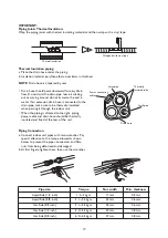
Page 17: ...leeve through the wall hole to keep the wall tidy and clean 3 Indoor Unit Piping Installation Fit the piping liquid and gas pipe and cables through the wall hole from outside or fit them from inside after completing indoor piping and cables connections so as to connect to outdoor unit Decide whether saw off the plastic part in accordance with the piping direction as shown below NOTE When fixing th...

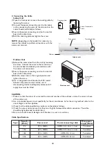
Page 18: ...unit When the piping is directed to the right piping power cable and drain hose should be thermally insulated and fixed at the rear of the unit Piping Connection a Connect indoor unit pipes with two wrenches Pay special attention to the torque allowed as shown below to prevent the pipes connectors and flare nuts from being deformed and damaged b At first fingers tighten them then use the wrenches ...

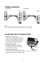
Page 19: ...ource and the unit A disconnecting device to adequately disconnect all supply lines must be fitted Covering plate Front panel Indoor unit Outdoor unit Terminal inside Cabinet Power Connection Cable 18 Access door Terminal inside Type Capacity Btu h Power cord Power connecting cable Main power supply Note Inverter 9k SJT 3 x 18AWG H07RN F 4G 1 0 mm 1 5 mm To indoor 12k H07RN F 4G 1 0 mm 1 5 mm To i...

Page 20: ...ous vibration or strong wind 3 Outdoor Unit Piping Connection Remove the valve caps from the 2 way and 3 way valve Connect the pipes to the 2 way and 3 way valves separately according to the required torque 4 Outdoor Unit Cable Connection see previous page Chassis Drain adapter Drain hose prepare by user Note For 9k 12k 18k models the power supply is connected from indoor unit with a plug For 24k ...

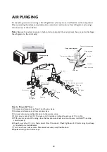
Page 21: ...ng a vacuum pump as shown below Note Because the system pressure is high and also to protect the environment be sure not to discharge the refrigerant to the air directly How to Purge Air Tubes 1 Unscrew and remove caps from 2 and 3 way valves 2 Unscrew and remove cap from service valve 3 Connect vacuum pump flexible hose to the service valve 4 Start vacuum pump for 10 15 minutes until it reaches a...

Page 22: ...are Centre Please give a short description of the fault the exact model of the air conditioner the serial number this is the number can be found on the side or on the bottom of the indoor unit your full address your telephone number If repair work has to be carried out contact the Customer Care Centre Use of original spare parts and a proper repair is guarenteed You will need to present the origin...

Reviews: