background image

Before you start...

Proper installation is your
responsibility. Make sure you
have everything necessary for
correct installation. It is the
responsibility of the installer to
comply with the installation
clearances specified on the
model/serial rating plate. The
model/serial rating plate is located
on the front of the downdraft vent
above the wiring box cover.

Check location where downdraft
vent will be installed. The location
should be away from strong draft
areas, such as windows, doors
and strong heating vents or fans.
Before making countertop cutout,
check that downdraft vent and
cooktop location will clear cabinet
walls, backsplash, and rear wall
studs inside cabinet.

ALL OPENINGS IN THE WALL OR
FLOOR WHERE RETRACTABLE
DOWNDRAFT VENT IS TO BE
INSTALLED MUST BE SEALED.

Important: Observe all governing
codes and ordinances.

This is the safety alert symbol.
This symbol alerts you to
hazards that can kill or hurt

you and others. All safety messages
will be preceded by the safety alert
symbol and the word “DANGER” or
“WARNING”. These words mean:

You can be killed or seriously injured
if you don’t follow instructions.

DANGER

WARNING

Your safety and the safety of

others is very important.

We have provided many important
safety messages in this manual and
on your appliance. Always read and
obey all safety messages.

All safety messages will identify the
hazard, tell you how to reduce the
chance of injury, and tell you what can
happen if the instructions are not
followed.

You will be killed or seriously injured
if you don’t follow instructions.

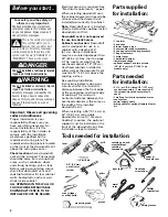
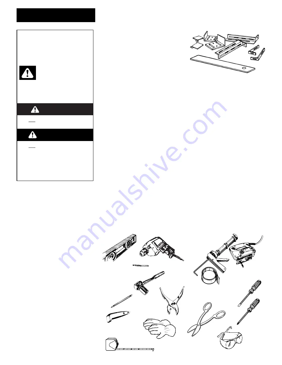
Parts supplied
for installation:

Parts needed 
for installation:

Tools needed for installation:

Phillips
screwdriver

flat-blade
screwdriver

caulking gun and
weatherproof
caulking 
compound

duct tape

metal
snips

pliers

pencil

saber or
keyhole saw

drill

1/8" drill bit

level

wire stripper
or utility knife

2

Electrical ground is required. See
“Electrical requirements,” page 3.

When installing downdraft vent,
the cabinet drawer will need to be
removed and the drawer front
installed permanently to cabinet.

Note: Downdraft vent is installed
directly behind the cooktop. Install
downdraft vent first.

Downdraft vent is not approved
for use in mobile homes.

Cabinet construction: Downdraft
vent is designed for use in a
cabinet with a depth of 24" 
(61 cm). Some installations
require a countertop deeper than
25" (63.5 cm). See chart on page
5. The maximum depth of the
overhead cabinet is 13" (33 cm).
Overhead cabinets installed at
either side of the downdraft vent
must be 18" (45.7 cm) above the
cooking surface. 

See cooktop Installation
Instructions before making any
cutouts and for the minimum
distance between the front edge
of the countertop and front edge
of cooktop. The minimum
horizontal distance between the
overhead cabinets is the same as
the width of the installed
downdraft vent.

When installing a 36" (91.4 cm) or
42" (106.7 cm) retractable
downdraft vent with “Create-A-
Cooktop” modules, the optional
support must be installed on the
front of the downdraft vent. See
installation steps for details.

3/8" (9.5 mm)
nut driver or
ratchet

gloves

measuring tape

safety glasses

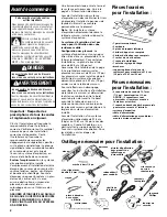
• 1 top trim
• 2 end caps
• 2 lower support legs
• 2 overcounter support brackets
• 2 undercounter mounting brackets
• 1 bag of fasteners
• 1 metal cover
• 1 backdraft damper
• literature package
• optional support and two screws

(36" (91.4 cm) or 42" (106.7 cm) 
models only)

• 2 U.L.- or C.S.A.-listed 1/2" (12.7 mm) 

conduit connectors (3 are required if
the exterior-mounted vent motor is
used.)

• 1 wall cap for interior-mounted motor
• vent system
• power supply cable
• wiring cable for optional remote blower

kit.

Summary of Contents for Vent system

Page 1: ...stallation steps Use and Care Information Accessories Installation Instructions and Use and Care Guide 30 76 2 cm 36 91 4 cm 42 106 7 cm Retractable Pop up Downdraft Vent Systems IMPORTANT Read and save these instructions IMPORTANT Installer Leave Installation Instructions with the homeowner Homeowner Keep Installation Instructions for future reference Save Installation Instructions for local elec...

Page 2: ...ulking gun and weatherproof caulking compound duct tape metal snips pliers pencil saber or keyhole saw drill 1 8 drill bit level wire stripper or utility knife 2 Electrical ground is required See Electrical requirements page 3 When installing downdraft vent the cabinet drawer will need to be removed and the drawer front installed permanently to cabinet Note Downdraft vent is installed directly beh...

Page 3: ...uate Do not ground to a gas pipe Check with a qualified electrician if you are not sure downdraft vent is properly grounded Do not have a fuse in the neutral or ground circuit IMPORTANT Save Installation instructions for electrical inspector s use E A U L or C S A listed 1 2 12 7 mm conduit connector must be provided at each end of the power supply cable at the downdraft vent and at the junction b...

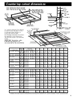
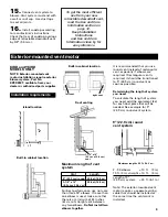
Page 4: ...9 5 mm centerline of cooktop cutout 3 1 4 x 10 8 3 cm x 25 4 cm See cooktop manufacturer s instructions for cooktop cutout depth and width Use dimensions for vent system cutout location that applies to your installation Vent system cutout dimensions for internal blower models only Exterior mounted blower systems connect with 9 22 9 cm round vent The cutout locations for this vent system will depen...

Page 5: ...5 4 cm 4 4 cm 79 7 cm 58 4 cm 63 5 cm RCC3024G GJC3034G 30 GZ7930XGS 29 1 2 27 1 2 20 1 2 2 2 30 23 25 3 4 76 2 cm GZ7930XHS 74 9 cm 69 9 cm 52 1 cm 5 1 cm 5 1 cm 76 2 cm 58 4 cm 65 4 cm RCS3004G RCS3014G 30 GZ7930XGS 28 7 8 27 1 2 19 2 1 2 3 31 1 2 23 25 1 2 YRCS3014G 76 2 cm GZ7930XHS 73 3 cm 69 9 cm 48 3 cm 6 4 cm 7 6 cm 80 0 cm 58 4 cm 64 8 cm KGCT365G KECT366G 36 KIRD861HSS KIRD862HSS 35 1 4 ...

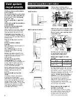
Page 6: ... a a a a a a a a a a a Vent system installed under a concrete slab using PVC sewer pipe wall cap 6 15 2 cm round PVC coupling 6 15 2 cm round PVC sewer pipe 6 15 2 cm round metal vent Tightly pack gravel or sand completely around pipe transition 6 15 2 cm round metal vent 6 15 2 cm round PVC coupling concrete slab 6 15 2 cm round PVC sewer pipe 6 15 2 cm round 90 PVC sewer pipe elbow 6 15 2 cm rou...

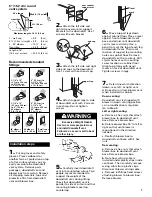
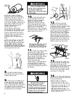
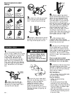
Page 7: ...eck that downdraft vent is parallel to side of cutout and that mounting brackets overlap countertop 6 Move support legs down against cabinet floor Place a level against front of downdraft vent base and adjust until downdraft vent is level vertically Use a pencil to mark the top of each leg on downdraft vent Then mark location of support leg mounting holes on cabinet floor Remove downdraft vent fro...

Page 8: ...slot over vent mounting hole and flange against countertop Attach other bracket to left side of downdraft vent Carefully drill starter holes through undercounter mounting brackets into underside of countertop Insert appropriate length screws into holes and tighten brackets to countertop When attaching undercounter bracket to underside of countertop make sure that the screw length will not go throu...

Page 9: ...16 8 m 8 3 cm x 35 6 cm Maximum length of vent system For best performance use no more than three 90 elbows If more than one elbow is used make sure that there is a minimum of 24 inches 61 cm of straight vent between any two elbows Do Not install two elbows together It is recommended that you use round vent instead of rectangular vent especially if elbows are required If rectangular vent is requir...

Page 10: ... of downdraft vent base and adjust position of legs until downdraft is level vertically Use a pencil to mark the top of each leg on face of downdraft vent Then mark location of support leg mounting holes on cabinet floor Remove downdraft vent from cutout Drill starter holes at each mounting screw location on cabinet floor Align top of legs with pencil marks on face of downdraft vent Tighten screws...

Page 11: ... white wires together with a twist on wire connector Connect the black wires together with a twist on connector Tighten the conduit connector clamp screws Reattach the vent box with 4 hex nuts wiring box cover green ground screw conduit connector 13 Turn power supply on Push and hold for a few seconds the button on the top of the downdraft vent Retractable section of downdraft vent will rise and b...

Page 12: ...ill result Use an extinguisher ONLY if You know you have a Class ABC extinguisher and you already know how to operate it The fire is small and contained in the area where it is started The fire department is being called You can fight the fire with your back to an exit Operating downdraft vent Push and hold for a few seconds the button on top of downdraft vent This slight delay prevents raising th...

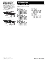
Page 13: ...1 862 36 91 4 cm one piece trim Part No 8171310 white Part No 8171311 black Part No 8171312 biscuit For model series KIRD YKIRD 821 822 42 106 7 cm one piece trim Part No 8171316 white Part No 8171317 black Part No 8171318 biscuit For model series GZ YGZ 7930 30 76 2 cm one piece trim Part No 8171300 white Part No 8171301 black For model series GZ YGZ 7736 36 91 4 cm one piece trim Part No 8171302...

Page 14: ...tructions d installation et Guide d utilisation et d entretien Système rétractable d aspiration par le bas 76 2 cm 30 po 91 4 cm 36 po 106 7 cm 42 po IMPORTANT Lire et conserver ces instructions IMPORTANT Installateur Remettre les instructions d installation au propriétaire de l appareil Propriétaire Conserver les instructions d installation pour consultation ultérieure Conserver les instructions ...

Page 15: ... 5 La profondeur maximum des placards muraux est de 33 cm 13 po Les placards muraux installés de part et d autre du système d aspiration doivent être placés à 45 7 cm 18 po au dessus de la table de cuisson Avant d effectuer un découpage consulter les instructions d installation de la table de cuisson et déterminer la distance minimale entre le bord avant du plan de travail et le bord avant de la t...

Page 16: ...er une tuyauterie de gaz pour la liaison à la terre En cas d incertitude quant à la qualité de la liaison à la terre de la hotte consulter un électricien qualifié Ne pas installer un fusible en série avec le conducteur neutre ou le conducteur de liaison à la terre IMPORTANT Conserver les instructions d installation à l intention de l inspecteur local des installations électriques E Un connecteur d...

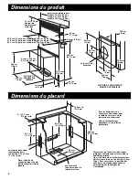
Page 17: ...ure pour la table de cuisson 8 3 cm x 25 4 cm 3 1 4 po x 10 po Pour les dimensions de l ouverture à découper pour la table de cuisson voir les instructions du fabricant Utiliser les dimensions applicables à l installation particulière Dimensions de l ouverture à découper indiquées seulement pour les modèles à ventilateur interne Un circuit doté d un ventilateur extérieur doit être raccordé à un co...

Page 18: ...100G 76 2 cm KIRD801HSS KIRD802HSS 73 3 cm 69 9 cm 48 3 cm 6 4 cm 8 6 cm 80 cm 58 4 cm 65 1 cm 30 po KIRD801XSS KIRD802XSS 28 7 8 po 27 1 2 po 19 po 2 1 2 po 3 3 8 po 31 1 2 po 23 po 25 5 8 po SCS3004G SCS3014G 76 2 cm GZ7930XGS 73 7 cm 69 9 cm 49 8 cm 5 4 cm 4 4 cm 79 7 cm 58 4 cm 63 5 cm GLT3014G 30 po GZ7930XHS 29 po 27 1 2 po 19 5 8 po 2 1 8 po 1 3 4 po 31 3 8 po 23 po 25 po RCC3024G GJC3034G ...

Page 19: ... a a a Circuit d évacuation installé sous une dalle de béton utilisation de tuyaux de PVC pour égout bouche de décharge murale raccord PVC diam 15 2 cm 6 po raccord PVC diam 15 2 cm 6 po tuyau PVC égout diam 15 2 cm 6 po tuyau PVC égout diam 15 2 cm 6 po conduit métallique diam 15 2 cm 6 po Gravier ou sable bien tassé tout autour du tuyau Gravier ou sable bien tassé tout autour du tuyau raccord de...

Page 20: ... que le système soit parfaitement vertical Avec un crayon marquer le sommet de chaque pied sur le système d aspiration Marquer ensuite la position des trous des pieds de support sur le plancher du placard Retirer le système d aspiration de l ouverture découpée Percer des avant trous à l emplacement de chaque vis sur le plancher du placard Aligner le sommet des pieds avec les marques de repérage tr...

Page 21: ...e d aspiration Fixer les pieds de support sur le plancher du placard 11 Fixer l une des brides de fixation sous le plan de travail au niveau de l angle avant supérieur droit du système d aspiration placer la fente sur le trou de montage et l autre section de la bride contre le plan de travail Fixer l autre bride de la même manière sur le côté gauche du système d aspiration Percer prudemment des av...

Page 22: ...n recommande l emploi de conduit rond plutôt que rectangulaire particulièrement s il est nécessaire d incorporer des coudes Si l emploi d une section de conduit rectangulaire est nécessaire effectuer la transition dès que c est possible avec du conduit rond de diam 22 9 cm 9 po Détermination de la longueur nécessaire du système Pour calculer la longueur effective du système de décharge on doit ten...

Page 23: ...rachable de l ouverture à utiliser pour l entrée du câble dans la boîte de connexion Le câble d alimentation à installer entre le ventilateur extérieur et la boîte de connexion du ventilateur n est pas fourni 9 Déterminer l emplacement d installation du ventilateur extérieur Découper dans le toit ou le mur l ouverture de passage du conduit d évacuation Inspecter le ventilateur à l extérieur Instal...

Page 24: ...ion Appuyer maintenir la pression pendant quelques secondes sur le bouton de commande au sommet du système d aspiration La section rétractable du système se soulève et le ventilateur se met en marche Positionner la garniture supérieure sur la section rétractable emboîter la garniture en place câble d alimentation du ventilateur extérieur bouton MARCHE ARRÊT bouton de commande du ventilateur embout...

Page 25: ... POMPIERS NE JAMAIS PRENDRE EN MAIN UN RÉCIPIENT ENFLAMMÉ le risque de brûlure est élevé NE PAS UTILISER D EAU ni un torchon humide ceci pourrait provoquer une explosion de vapeur brûlante Utiliser un extincteur SEULEMENT si Il s agit d un extincteur de classe ABC dont on connaît le fonctionnement Il s agit d un petit feu encore limité à l endroit où il s est déclaré Les pompiers ont été contactés...

Page 26: ...ur les modèles KIRD et YKIRD 861 862 Garniture monopièce de 91 4 cm 36 po Pièce n 8171310 blanc Pièce n 8171311 noir Pièce n 8171312 biscuit Pour les modèles KIRD et YKIRD 821 822 Garniture monopièce de 106 7 cm 42 po Pièce n 8171316 blanc Pièce n 8171317 noir Pièce n 8171318 biscuit Pour les modèles GZ et YGZ 7930 Garniture monopièce de 76 2 cm 30 po Pièce n 8171300 blanc Pièce n 8171301 noir Pou...

Reviews: