10
8.
Replace terminal box cover.
9.
Check all light bulbs to make sure they are secure in their
sockets.
10.
Reconnect power.
Complete Installation
1.
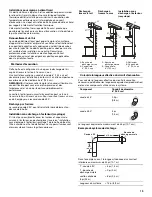
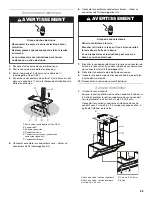
Install vent cover.
Push lower cover down onto hood and lift upper cover to
ceiling and install with two 2.9 x 9.5 mm screws.
Connect the upper and lower vent covers with
two 3.5 x 9.5 mm screws apiece from the inside of the hood.
Install Filters
1.
For non-vented (recirculating) installations, install charcoal
filter over grille on blower housing and turn filter handle
clockwise. Repeat with other charcoal filter.
2.
For all installations, insert back edge or metal filter into rear
channel of the filter opening.
3.
Push handle toward the rear and push filter up.
4.
Pull filter toward the front and insert into front channel.
Check Operation
1.
Press the light button
. The light should turn on.
2.
Press the “1” button. The blower should operate.
3.
Press the “1” button for low speed, “2” button for medium
speed or “3” button for high speed.
4.
Press the “0” button to turn off the blower.
5.
If range hood does not operate, check to see whether a
circuit breaker has tripped or a household fuse has blown.
6.
Disconnect power supply.
7.
Check that the wiring is correct.
8.
Replace all parts and panels before operating.
9.
Reconnect power.
NOTE:
To get the most efficient use from your new range hood,
read the “Range Hood Use” section.
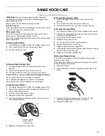
RANGE HOOD USE
Operation
The canopy hood is designed to remove smoke, cooking vapors
and odors from the cooktop area. For best results, start the hood
before cooking and allow it to operate several minutes after the
cooking is complete to clear all smoke and odors from the
kitchen.
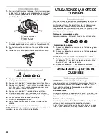
Hood control panel
The hood controls are located on the front side of the canopy.
Operating the light
1.
Press the light button
to turn on the light.
2.
Press the light button
to turn off the light.
Operating the blower and adjusting blower speed
1.
Press the “1” button for low speed, “2” button for medium
speed, “3” button for high speed.
2.
Press the “0” button to turn off the blower.
A. Upper vent cover
B. Lower vent cover
C. 2.9 x 9.5 mm screws
D. 3.5 x 9.5 mm screws
E. Bracket
A. Blower housing
B. Filter handle
C. Charcoal filters
A
B
D
C
C
E
A
B
C
C
0
1
2
3
0
1
2
3
Summary of Contents for W10029770A
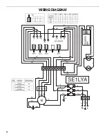
Page 12: ...12 WIRING DIAGRAM ...

