FOR SERVICE TECHNICIAN ONLY - DO NOT REMOVE OR DESTROY
PAGE 20
2.
Plug in dryer or reconnect power.
3.
Perform steps under DIAGNOSTIC: Console
Buttons and Indicators, page 2, to verify repair.
TEST #7 Door Switch
Refer to page 2 and perform steps under
Activating the Diagnostic Test Mode. Then
perform steps under DIAGNOSTIC: Door Switch,
page 3. Functionality is verified with a beep
each time the door is closed and opened, and
an alphanumeric number appears in the display.
If any of the preceding conditions are not met:
1.
Unplug dryer or disconnect power.
2.
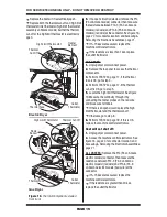
Check that the wires between the door switch
and machine control electronics are connected.
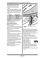
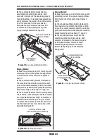
See figure 12 for switch location, and see
Accessing & Removing the Electronic Assemblies,
page 21.
If the connections are OK, replace the wire
and door switch assembly and retest.
If wire and door switch assembly have been
replaced and dryer still does not start, replace the
machine control electronics.
TEST #8 Water Valve
(Steam Models Only)
Activate the Diagnostic Test Mode as shown
on page 2. Press Start (Start/Pause on Maytag
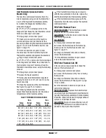
models) and verify that water is being sprayed
in the drum. See figure 13.
If no water is sprayed in the drum:
1.
Perform steps in Accessing & Removing the
Electronic Assemblies, page 21, and check that
the wires are connected to the water valve relay
on the machine control electronics. See figure 16,
page 22.
2.
Check that water is hooked up and turned on.
3.
Inside the drum, unscrew and replace the
water nozzle using a 7/16" wrench or socket.
4.
Remove the back panel, then:
Check that the wires and hose are connected
to the water valve assembly.
Check that the water valve assembly hose is
connected to the nozzle.
5.
If everything is hooked up and the water still
does not dispense:
Unplug dryer or disconnect power.
Replace the valve assembly.
6.
Plug in dryer or reconnect power.
7.
Activate the Service Diagnostic Test Mode,
page 2, and check to make sure water is being
sprayed into the drum.
FRONT
Door Switch
TOP OF
DRUM
Figure 12.
Door switch location.
Water Valve Wires
Water Nozzle
Water Valve Assembly
Figure 13.
Water system components.

