background image

8

Gas Supply Line 

Provide a gas supply line of 

³⁄₄

" (1.9 cm) rigid pipe to the 

cooktop location. A smaller size pipe on longer runs may 
result in insufficient gas supply. Pipe-joint compounds that 
resist the action of LP gas must be used. Do not use 
TEFLON

®†

 tape. With LP gas, piping or tubing size should be 

½" minimum. Usually, LP gas suppliers determine the size 
and materials used in the system.

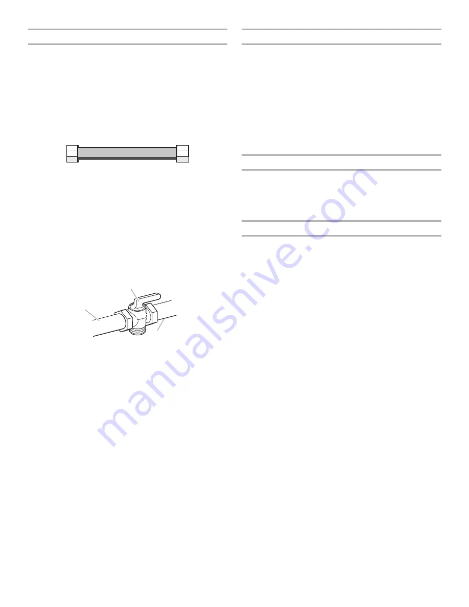
Flexible metal appliance connector:

If local codes permit, use a 

¹⁄₂

" or 

³⁄₄

" I.D. flexible stainless 

steel tubing gas connector, designed by CSA to connect 
the cooktop to the rigid gas supply line. 

A ½" male pipe thread is needed for connection to the 
female pipe threads of the inlet to the cooktop pressure 
regulator. 

Do not kink or damage the flexible metal tubing when 
moving the cooktop.

Must include a shutoff valve: 
The supply line must be equipped with a manual shutoff 
valve. This valve should be located in the same room but 
external to the cooktop opening, such as an adjacent 
cabinet. It must be accessible without removing the cooktop, 
and it should be in a location that allows ease of opening and 
closing. Do not block access to shutoff valve. The valve is for 
turning on or shutting off gas to the cooktop.

Gas Pressure Regulator

The gas pressure regulator supplied with this cooktop must be 
used. The inlet pressure to the regulator should be as follows for 
proper operation:

Natural Gas:

Minimum pressure: 5" (12.7 cm) WCP

Maximum pressure: 7" to 14" (17.8 cm to 35.5 cm) WCP

LP Gas:

Minimum pressure: 10" (25.4 cm) WCP

Maximum pressure: 14" (35.5 cm) WCP

Contact local gas supplier if you are not sure about the inlet 
pressure.

Burner Input Requirements

Input ratings shown on the model/serial rating plate are for 
elevations up to 2,000 ft (609.6 m). 

For elevations above 2,000 ft (609.6 m), ratings should be 
reduced at a rate of 4% for each 1,000 ft (304.8 m) above sea 
level (not applicable for Canada). 

Gas Supply Pressure Testing

Gas supply pressure for testing regulator must be at least 
1" water column pressure above the manifold pressure shown on 
the model/serial rating plate.

Line pressure testing above ½ psi gauge (14" WCP)

The cooktop and its individual shutoff valve must be 
disconnected from the gas supply piping system during any 
pressure testing of that system at test pressures in excess of 
½ psi (3.5 kPa).

Line pressure testing at ½ psi gauge (14" WCP) or lower

The cooktop must be isolated from the gas supply piping system 
by closing its individual manual shutoff valve during any pressure 
testing of the gas supply piping system at test pressures equal to 
or less than ½ psi (3.5 kPa).

A. Gas supply line
B. Shutoff valve “open” position

C. To cooktop

†®TEFLON is a registered trademark of E.I. Du Pont De Nemours and Company.

A

B

C

Summary of Contents for W10597144A

Page 1: ...tallation 11 SÉCURITÉ DE LA TABLE DE CUISSON 13 EXIGENCES D INSTALLATION 14 Outillage et pièces 14 Exigences d emplacement 14 Spécifications électriques 18 Spécifications de l alimentation en gaz 18 INSTRUCTIONS D INSTALLATION 20 Installation de la table de cuisson 20 Raccordement au gaz 20 Achever l installation 22 W10597144A IMPORTANT Installer Leave installation instructions with the homeowner ...

Page 2: ...g property damage personal injury or death Do not store or use gasoline or other flammable vapors and liquids in the vicinity of this or any other appliance WHAT TO DO IF YOU SMELL GAS Do not try to light any appliance Do not touch any electrical switch Do not use any phone in your building Immediately call your gas supplier from a neighbor s phone Follow the gas supplier s instructions If you can...

Page 3: ... floor where cooktop is to be installed must be sealed Cabinet opening dimensions that are shown must be used Given dimensions are minimum clearances Grounded electrical supply is required See Electrical Requirements section Proper gas supply connection must be available See Gas Supply Requirements section The cooktop is designed to hang from the countertop by its side or rear flanges The gas and ...

Page 4: ... 19 49 2 cm D 28 72 1 cm E 3 9 2 cm F 4 11 6 cm G 1 3 4 cm A 21 53 3 cm B 30 76 2 cm C 18 48 0 cm D 28 72 1 cm E 3 8 6 cm F 4 10 5 cm G 1 3 8 cm A C D B E F G A B C D E F G A 21 53 3 cm B 36 92 0 cm C 19 49 2 cm D 34 88 1 cm E 3 9 2 cm F 4 11 6 cm G 1 3 6 cm A 21 53 3 cm B 36 91 4 cm C 18 48 0 cm D 33 85 7 cm E 3 8 6 cm F 4 10 5 cm G 1 3 8 cm A B C D E F G D A B C E F G ...

Page 5: ...top platform and bottom of uncovered wood or metal cabinet 24 61 cm minimum clearance if bottom of wood or metal cabinet is covered by not less than 0 6 cm flame retardant millboard covered with not less than No 28 MSG sheet steel 0 015 0 04 cm stainless steel or 0 024 0 06 cm aluminum or 0 020 0 05 cm copper E 36 91 4 cm top of countertop to floor F Gas line opening Wall anywhere 5 12 7 cm below ...

Page 6: ... Front Edge H I B A C D E Cutout Product Opening Dimensions 30 76 2 cm Models Models A B Min Recommended Max Min Recommended Max KCGS550 and KCGS950 All Other 30 76 2 cm Models 28 72 4 cm 28 72 4 cm 28 73 4 cm 28 73 4 cm 29 74 3 cm 29 74 3 cm 19 49 5 cm 19 48 3 cm 19 50 2 cm 19 49 5 cm 20 50 8 cm 20 50 8 cm 36 91 4 cm Models KCGS556 and KCGS956 All Other 36 91 4 cm Models 34 88 4 cm 33 86 0 cm 35 ...

Page 7: ...atest edition IMPORTANT Leak testing of the cooktop must be conducted according to the manufacturer s instructions Type of Gas Natural Gas This cooktop is design certified by CSA International for use with Natural gas or after proper conversion for use with LP gas This cooktop is factory set for use with Natural gas If converting to LP gas see the LP Gas Conversion instructions provided in the pac...

Page 8: ...ied with this cooktop must be used The inlet pressure to the regulator should be as follows for proper operation Natural Gas Minimum pressure 5 12 7 cm WCP Maximum pressure 7 to 14 17 8 cm to 35 5 cm WCP LP Gas Minimum pressure 10 25 4 cm WCP Maximum pressure 14 35 5 cm WCP Contact local gas supplier if you are not sure about the inlet pressure Burner Input Requirements Input ratings shown on the ...

Page 9: ...he smaller thread ends of the flexible connector adapters see C and G in the following illustration 2 Attach one adapter to the gas pressure regulator and the other adapter to the gas shutoff valve Tighten both adapters A Attachment screw holes for optional front and back location B Cooktop base bottom C Attachment screw D Clamping bracket end locations recommended A Edge of cooktop base bottom B ...

Page 10: ...nd grates from parts package Align notches in burner caps with pins in burner base Align orifice holder in burner base with igniter electrode Burner caps should be level when properly positioned If burner caps are not properly positioned surface burners will not light Place burner grates over burners and caps No appliance obstructions below cooktop Suggested installation to avoid interference belo...

Page 11: ...et to the open position Check that burner caps are properly positioned on burner bases Recheck operation of surface burners If a burner does not light at this point contact your dealer or authorized service company for assistance Check Flame Height Adjust the height of surface burner flames The surface burner low flame should be a steady blue flame approximately 6 4 mm high Adjustment for Single V...

Reviews: