background image

17

INSTALLING LEVELING LEGS, COIN SLIDE, AND COIN BOX

The coin slide mechanism, control panel lock and key, and 
coin box lock and key are not included and are available from 
usual industry sources. A special coin slide extension must be 
used on this model and can be purchased from the coin slide 
distributor.

1.  Prepare dryer for leveling legs
NOTE: 

Slide dryer onto cardboard or hardboard before moving 

to avoid damaging floor covering. 

Using two or more people, move dryer to desired installation 
location. 
Take tape off front corners of dryer. Open dryer and remove  
the literature and parts packages. Wipe drum interior with damp 
cloth to remove any dust. 
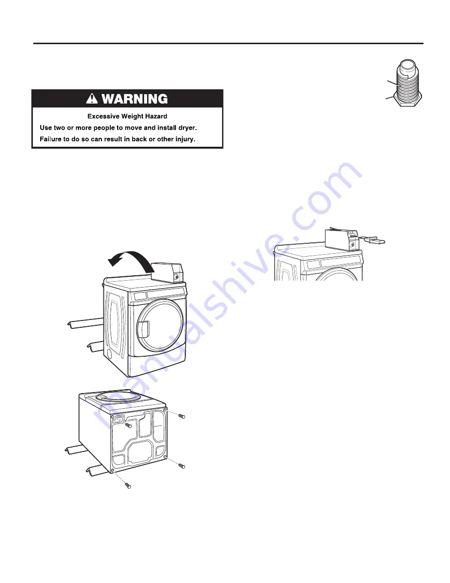
Take two cardboard corners from the dryer carton and place 
them on the floor in back of the dryer. Firmly grasp body of  
the dryer and gently lay it on its back on the cardboard corners.

2.  Screw in leveling legs 

Examine leveling legs and find diamond  
marking. Screw legs into leg holes by  
hand. Use an adjustable wrench or 1" 
(25 mm) hex-head socket wrench to  
finish turning legs until diamond marking  
is no longer visible. Then fit a covered foot 
boot over each leg foot. For floors with  
greater slopes, a longer leveling foot  
(part no. 279810) is available.
To protect the floor, use a large piece of cardboard from the 
dryer carton. Stand dryer up on the cardboard. Slide the dryer 
until it is close to its final location. Leave enough room for 
electrical connection and to connect the exhaust vent.

On some models: 

The meter case houses the factory-installed 

coin slide mechanism, service lock and key, and coin box lock 
and key.

3.  Install coin slide and coin box 

Remove the service door of the meter case by lifting  
it up at the back. Install the money-accepting device.  
(Refer to manufacturer’s instructions for proper installation.)

Replace the meter case service door. Put the coin vault with 
lock and key in the meter case opening.
Remove cardboard or hardboard from under dryer. Adjust  
the legs of the dryer up or down until the dryer is level.

Foot

Diamond 
Marking

Summary of Contents for W10919522B

Page 1: ...INSTALLATION INSTRUCTIONS Commercial Dryer Gas or Electric www whirlpoolcommerciallaundry com W10919522B W10919523B SP INSTRUCTIONS D INSTALLATION Sécheuse à usage commercial à gaz ou électrique ...

Page 2: ...VELING 24 COMPLETE INSTALLATION 24 REVERSING DRYER DOOR SWING 25 MAINTENANCE INSTRUCTIONS 27 IF YOU NEED ASSISTANCE 27 ELECTRONIC CONTROL SETUP INSTRUCTIONS 28 WARRANTY 34 TABLE DES MATIÈRES Page SÉCURITÉ DE LA SÉCHEUSE 35 EXIGENCES D INSTALLATION 38 Outils et pièces 38 Dimensions Distances de dégagement 39 Exigences concernant l évacuation 40 Exigences d installation pour la sécheuse à gaz 43 Exi...

Page 3: ...O DO IF YOU SMELL GAS Do not try to light any appliance Do not touch any electrical switch do not use any phone in your building Immediately call your gas supplier from a neighbor s phone Follow the gas supplier s instructions If you cannot reach your gas supplier call the fire department Installation and service must be performed by a qualified installer service agency or the gas supplier Clear t...

Page 4: ...with the National Fuel Gas Code ANSI Z223 1 NFPA 54 or the Natural Gas and Propane Installation Code CSA B149 1 The dryer must be electrically grounded in accordance with local codes or in the absence of local codes with the National Electrical Code ANSI NFPA 70 or the Canadian Electrical Code Part 1 CSA C22 1 ...

Page 5: ... mm Nut Driver 27 686 mm Wood Block Caulk Gun and Caulk Vent Clamps Pipe Joint Compound Putty Knife for installing new exhaust vent suitable for gas type Flashlight optional 1 25 mm Ruler or Measuring Tape Open End Wrenches INSTALLATION REQUIREMENTS TORX and T20 are registered trademarks of Acument Intellectual Properties LLC Parts Supplied Foot Boots 4 Leveling Legs 4 Tools and Parts To locate fa...

Page 6: ...6 INSTALLATION REQUIREMENTS Front View Side View Back View Dimensions Clearances Recessed Front View Closet Side View Bottom Exhaust Dimensions Clearances 0 0 mm ...

Page 7: ... is not plugged with lint Replace plastic or metal foil vents with rigid metal or flexible metal vents Review Vent System Chart and if necessary modify existing vent system to achieve best drying performance NOTE Although each single load dryer should typically have an unobstructed outdoor air opening of 24 2 154 cm2 based on 1 6 5 cm per 1 000 Btu 252 kcal common make up air openings are also acc...

Page 8: ...s sections A 4 102 mm outlet hood is preferred However a 21 2 64 mm outlet exhaust hood may be used A 21 2 64 mm outlet creates greater back pressure than other hood types For permanent installation a stationary vent system is required Connect Vent 1 If connecting to existing vent make sure the vent is clean 2 Using a 4 102 mm clamp connect vent to exhaust outlet in dryer NOTE Do not remove vent c...

Page 9: ... draft Damper Kit is available from your distributor and should be installed in the vent of each dryer to keep exhausted air from returning into dryers and to keep exhaust in balance within main vent Unobstructed return air openings are required Each vent should enter the main vent at an angle pointing in the direction of the airflow Vents entering from the opposite side should be staggered to red...

Page 10: ...rdinances Q Check code requirements Some codes limit or do not permit installation of clothes dryers in garages closets or sleeping quarters Contact your local building inspector Q Make sure that lower edges of the cabinet plus the back and bottom sides of the dryer are free of obstructions to permit adequate clearance of air openings for combustion air See Recessed Area and Closet Installation In...

Page 11: ...dinances If a mating outlet is not available it is the personal responsibility and obligation of the customer to have the properly grounded outlet installed by a qualified electrician Q If codes permit and a separate ground wire is used it is recommended that a qualified electrician determine that the ground path is adequate Q Check with a qualified electrician if you are not sure the dryer is pro...

Page 12: ...to this elevation Gas Supply INSTALLATION REQUIREMENTS When installed above 10 000 feet 3048 m a four percent 4 reduction of the burner B T U rating shown on the model serial plate is required for each 1 000 foot 305 m increase in elevation For assistance when converting to other gas types and or installing above 10 000 feet 3048 m elevation contact your local service company Gas supply pressure r...

Page 13: ...t test pressures equal to or less than 1 2 psig 352 kg m2 Expected Pressures For Gas Supply Minimum Inches of Water Maximum Inches of Water Natural Gas 5 2 10 5 Propane Gas 8 0 13 0 Alternate Method The gas supply may also be connected using 3 8 10 mm approved copper or aluminum tubing If the total length of the supply line is more than 20 ft 6 1 m larger tubing will be required If using natural g...

Page 14: ... be considered for ease of installation servicing and compliance with local codes and ordinances If closet door is installed the minimum unobstructed air opening in the top and bottom is required Louvered doors with equivalent air openings are acceptable Location Requirements The dryer must be exhausted outdoors 24 in 2 155 cm2 48 in 2 310 cm2 3 76 mm 3 76 mm Closet door Front View INSTALLATION RE...

Page 15: ...he neutral is prohibited for 1 new branch circuit installations and 2 areas where local codes prohibit grounding through the neutral conductor Electric Dryer Power Supply Cord If using a power supply cord Use a UL listed power supply cord kit marked for use with clothes dryers The kit should contain Q A UL listed 30 amp power supply cord rated 120 240 volt minimum The cord should be type SRD or SR...

Page 16: ...to a standard 14 30R wall receptacle The cord is 5 ft 1 52 m in length Be sure wall receptacle is within reach of dryer s final location Q Do not use an extension cord If you are using a replacement power supply cord it is recommended that you use Power Supply Cord Replacement Part Number 8579325 For further information please reference the service numbers located in the Assistance or Service sect...

Page 17: ... marking Screw legs into leg holes by hand Use an adjustable wrench or 1 25 mm hex head socket wrench to finish turning legs until diamond marking is no longer visible Then fit a covered foot boot over each leg foot For floors with greater slopes a longer leveling foot part no 279810 is available To protect the floor use a large piece of cardboard from the dryer carton Stand dryer up on the cardbo...

Page 18: ...el by using a 1 4 nutdriver to remove the 2 hex head screws from the bottom of the panel Then lift up on the panel while pulling the bottom of the panel away from the dryer 3 Open the shut off valve in the gas supply line and make sure the dryer has its own gas supply opened 4 Test all connections by brushing on an approved noncorrosive leak detection solution Bubbles will show a leak Correct any ...

Page 19: ... Insert power cord into strain relief Remove Terminal Block Cover Strain Relief INSTALLATION INSTRUCTIONS ELECTRIC DRYER Direct Wire Strain Relief 1 Insert strain relief 2 Insert conduit into strain relief and tighten clamp Electric Dryer Electrical Connections ...

Page 20: ...ground connector screw 2 Connect ground and neutral wire to center terminal block Connection Options Connecting 4 Wire Connection Power Supply Cord IMPORTANT A 4 wire connection is required for mobile homes and where local codes do not permit the use of 3 wire connections Direct Wire 4 wire direct 3 wire direct 1 25 mm 5 127 mm Connecting Power Cord Ground Wire 3 Connect ground wire green or bare ...

Page 21: ... connections Direct wire cable must have 5 ft 1 52 m of extra length so dryer can be moved if needed Strip 5 127 mm of outer covering from end of cable leaving bare ground wire at 5 127 mm Cut 11 2 38 mm from 3 remaining wires Strip insulation back 1 25 mm Shape ends of wires into a hook shape Connecting 3 Wire Connection Power Supply Cord Connecting 4 Wire Connection Direct Wire INSTALLATION INST...

Page 22: ...eutral wire Direct wire cable must have 5 ft 1 52 m of extra length so dryer can be moved if needed Strip 31 2 89 mm of outer covering from end of cable Strip insulation back 1 25 mm If using 3 wire cable with ground wire cut bare wire even with outer covering Shape ends of wires into a hook shape Connecting Neutral Wire 1 Loosen or remove center terminal block screw Connecting Remaining Wires 4 C...

Page 23: ... Use for direct wire or power supply cord where local codes do not permit connecting cabinet ground conductor to neutral wire Connecting Neutral Wire 1 Remove center terminal block screw Also remove neutral ground wire by removing external ground conductor screw 2 Connect neutral wire and neutral wire of power supply cord cable to center terminal block Connecting 3 Wire Connection Optional ...

Page 24: ...epeat five minute test 8 If drying time is too long make sure that the lint screen is clean and that there are no obstructions to airflow in the dryer vent system 9 Restart the dryer and allow it to complete a full cycle to make sure it is working properly COMPLETE INSTALLATION LEVELING Not Level LEVEL Not Level 1 Remove cardboard from beneath dryer Place a level on top edges of dryer checking eac...

Page 25: ...ff the screw 3 Lay the door assembly on a previously prepared flat surface with the inside inner door assembly facing up and remove 6 phillips head screws to release outer door assembly from inner door assembly NOTE It is important that you remove only the 6 indicated screws 4 Lift the inner door assembly off outer door assembly 5 Remove 4 Phillips head screws to release center insert from outer d...

Page 26: ...o other side Reinstall 4 screws 4 Reinstall plug strips on opposite side of the inner door 5 Check for fingerprints on the glass Clean if necessary Replace the Door Assembly 1 Place the inner door assembly inside the outer door assembly 2 Reassemble the inner and outer door assemblies with the 6 screws Reverse the strike 1 Use a small flat blade screwdriver to remove plug strip from the dryer door...

Page 27: ...ryer clear and free from combustible materials gasoline and other flammable vapors and liquids Q Keep dryer area clear and free of items that would obstruct the flow of combustion and ventilation air If dryer does not operate check the following Q Electrical supply is connected Q Circuit breaker is not tripped or house fuse is not blown Q Door is closed Listen closely to hear the door switch activ...

Page 28: ...edit is given for coins dropped with 99 minutes in the display Accumulator Pricing If option d is set to d 00 and the 6 code is set to one coin 1 then accumulator pricing is in effect Cycle time can be purchased one coin at a time up to the maximum time of 99 minutes Fixed Cycle With Top Off Pricing available for use with coin drops or card readers only A dryer set to offer Top Off capability will...

Page 29: ...de is indicated by the one or two left hand characters The set up code value is indicated by the two or three right hand characters NOTE The first line of each code indicates the factory default Code Explanation 6 06 REGULAR CYCLE PRICE 6 06 When the d xx is set to d 00 this 6 xx value represents the number of coins coin 1 needed to start the dryer may adjust from 0 39 Change this value by pressin...

Page 30: ... 24 hr clock 7 00 This is the start hour select 0 23 hours Select START HOUR by pressing the COTTON WHITES button Press the PERM PRESS button once to advance to next code Code Explanation 8 00 SPECIAL PRICE STOP HOUR NOTE Uses military time 24 hr clock 8 00 This is the stop hour select 0 23 hours Select STOP HOUR by pressing the COTTON WHITES button Press the PERM PRESS button once to advance to n...

Page 31: ... WHITES button there is an option of 1 199 nickels C 05 When a Gen 2 card reader is used this code represents the value of top off in nickels C 05 0 25 Press the PERM PRESS button once to advance to next code d 00 COIN SLIDE OPTION This option is either Selected ON or Not Selected OFF Replacement of meter case will be needed for coin slide mounting d 00 Not Selected OFF d CS Selected ON NOTE This ...

Page 32: ... cleared F 73 UI Microprocessor is not able to read or verify EEPROM cycles and price display disabled until diagnostic code is manually cleared F 74 UI EEPROM memory is a CRC failure cycles and price display disabled until diagnostic code is manually cleared Dryer Diagnostic Mode This mode is entered by pressing COLORS DELICATES for one second while in either of the set up codes 6 xx or 7 xx or w...

Page 33: ...code number 8 SC XX CCU software revision where XX is the software revision number 9 SU XX UI software revision where XX is the software number 10 EU XX UI EEPROM revision where XX is the EEPROM number To erase the 3 help codes press COLORS DELICATES button The Errors displayed in this section are the history errors that have occurred in the dryer not necessarily an error that is in progress The c...

Page 34: ...or furnished with the product Whirlpool will pay for factory specified replacement parts to correct defects in materials or workmanship that existed when this commercial appliance was purchased YOUR SOLE AND EXCLUSIVE REMEDY UNDER THIS LIMITED WARRANTY SHALL BE PRODUCT REPAIR AS PROVIDED HEREIN Whirlpool recommends that you use an in network service provider to diagnose and repair your Commercial ...

Reviews: