15
Variable-Speed Motor
Units equipped with a variable-speed circulation air blower motor
will deliver a constant airflow within a wide range of external
static pressures. For other features of this variable-speed motor,
see “Adjust Blower Speed Variable-Speed Motor Only.”
Start/Stop
The variable-speed motor will slowly ramp up to normal
operating speed. This minimizes noise and increases comfort by
eliminating the initial blasts of air encountered with standard
motors. At the end of a cooling or heating cycle, the motor will
slowly ramp down.
Controls
Limit Control
This control is located inside the heating compartment and is
designed to open at abnormally high air temperatures. It resets
automatically. The limit control operates when a high temperature
condition, caused by inadequate airflow, occurs. This causes the
ignition control to close the gas control valve. The circulation air
blower continues to operate in this situation.
Pressure Switch
The pressure switch prevents the gas control valve and igniter
from being energized if there is insufficient combustion air due to
a failed combustion blower or a blocked vent.
Flame Sensor
If the ignition control does not receive a signal from the flame
sensor indicating that the burners have established flame, the
gas control valve closes after the 10-second trial for ignition
period.
Rollout Switch
The switch is located above the main burners. In the event of a
sustained flame rollout, the rollout switch causes the ignition
control to close the gas control valve. To reset, push the button
on top of the switch.
Auxiliary Limit (42, 48 and 60 units only)
This control is located in the side of the circulation air blower
housing. The switch causes the ignition control to close the gas
control valve should the circulation blower fail to operate. This
control resets automatically.
TROUBLESHOOTING
Furnace Fails to Operate Properly
Review “Sequence of Operation” and visually inspect the
following before troubleshooting:
Is the power to the furnace on?
Is the manual gas shutoff valve to the furnace open?
Failure Codes
The furnace has a built-in, self-diagnostic capability. The furnace
control continuously monitors its own operation and the
operation of the system. If a system problem occurs, the LED on
the furnace control board flashes a failure code.
See the Failure Codes chart for a description of the LED flash
codes.
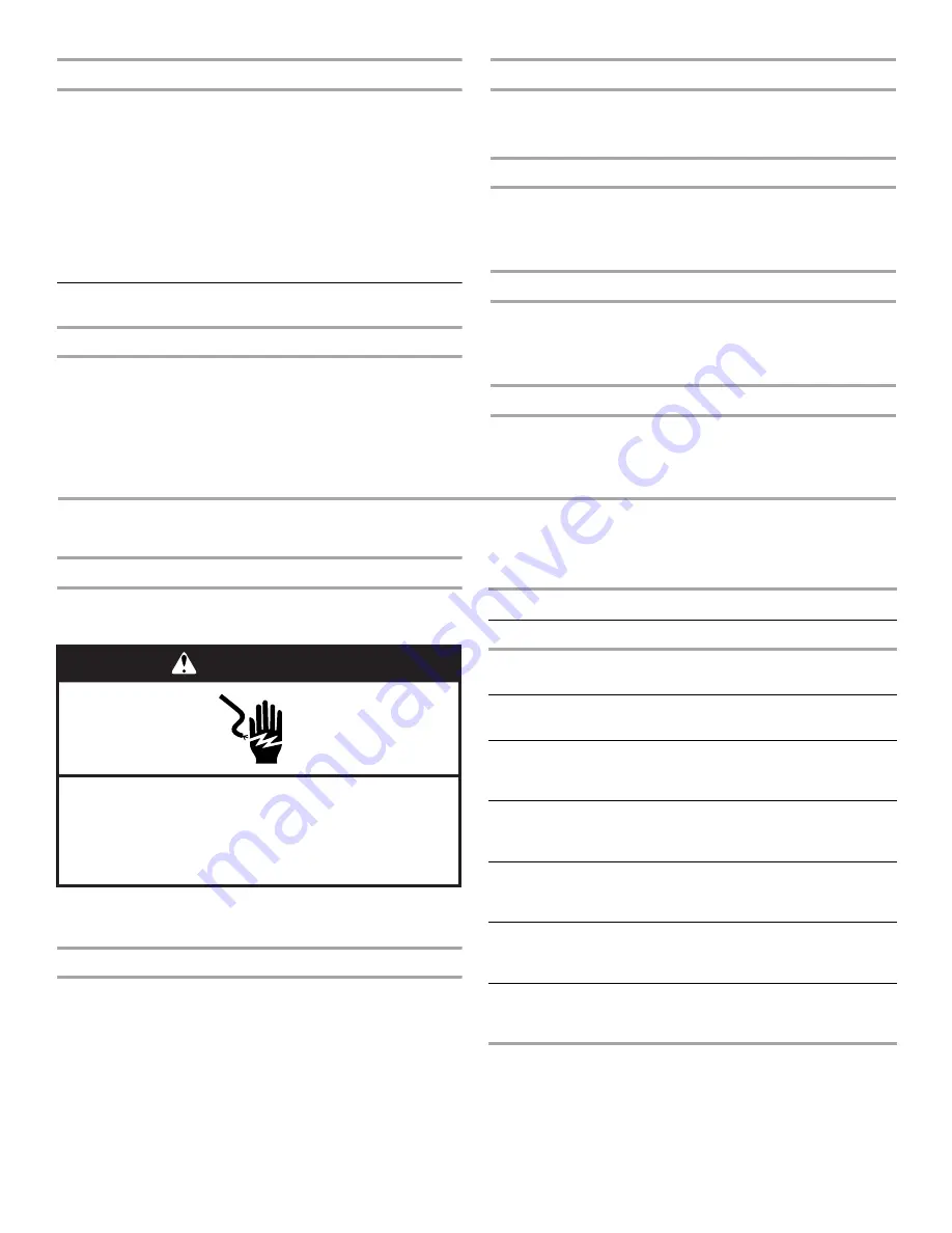
WARNING
Electrical Shock Hazard
Disconnect power before servicing.
Replace all parts and panels before operating.
Failure to do so can result in death or electrical shock.
Failure Codes
LED Status
Flashing Rate
Fault Description
Slow Flash
One flash per second
Normal Operation:
No call for heat
Fast Flash
Two flashes per
second
Normal operation:
Call for heat
2 Flashes
Two flashes per
second with 1-second
pause
System lockout:
Failed to detect or
sustain flame
3 Flashes
Three flashes in
1.5 seconds with
1-second pause
Pressure switch
open or closed
4 Flashes
Four flashes in
2 seconds with
1-second pause
High limit or rollout
switch open
5 Flashes
Five flashes in 2.5
seconds with 1-second
pause
Flame sensed and
gas valve not
energized
Steady
-
Internal failure:
Micro-controller
failure; self-check


