16
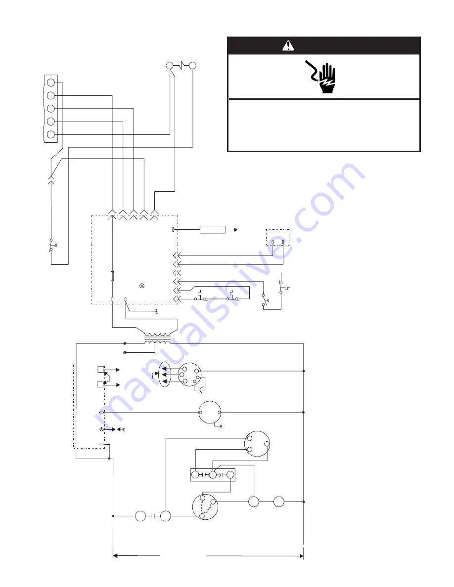
Wiring Connection Diagram—Single Phase, Multi-Speed
YG
W1
RC
Y
G
W
R
C
BU
G
Y
W
R
24V
A
C
1
625
4
3
Flame
Flame
Sense
GY
BR
BU
OR
R
BK
W
PR
BK
G
PR
OR
W
PR
Main
Limit
Switch
R
ollout
Switch
Pressure
Switch
A
ux.
Limit
Switch
(If used)
Gas
Valve
Fuse
Ignition Control
BU
Y
R
Y
Contactor
Thermostat
Y
Y
High Pressure
Switch
(If used)
L1
T1
T2
L2
C
H
F
Condenser
F
an Motor
Compressor
Contactor
Compressor
Contactor
Dual
Capacitor
Compressor
Transformer
C
S
R
L1
CMB BL
WR
Spark
Comb.
Air
Blower
Ignition Control
BK
W
L2
L1
BK
BR
PR
R
R
BK
208V
240V
24V
Indoor
Blower
M
otor
BK
S4
S1
K1
A3
GV1
S21
S18
S47
S10
T1
B3
B6
B4
K1-2
C12
B1
K1-1
A3
Ground
BU
Y
LED
Y
E1
C4
Capacitor
H
M
L
C
ACB
Cool
ACB
Heat
BK
BU
Jumper (installed
on some models)
See Blower
Speed Chart
For Wiring
208/230V-1-60
Wiring Connection Diagram
Single Stage Heat, Single Phase
P/N 48129-001
WARNING
Electrical Shock Hazard
Disconnect power before servicing.
Replace all parts and panels before operating.
Failure to do so can result in death or electrical shock.


