17
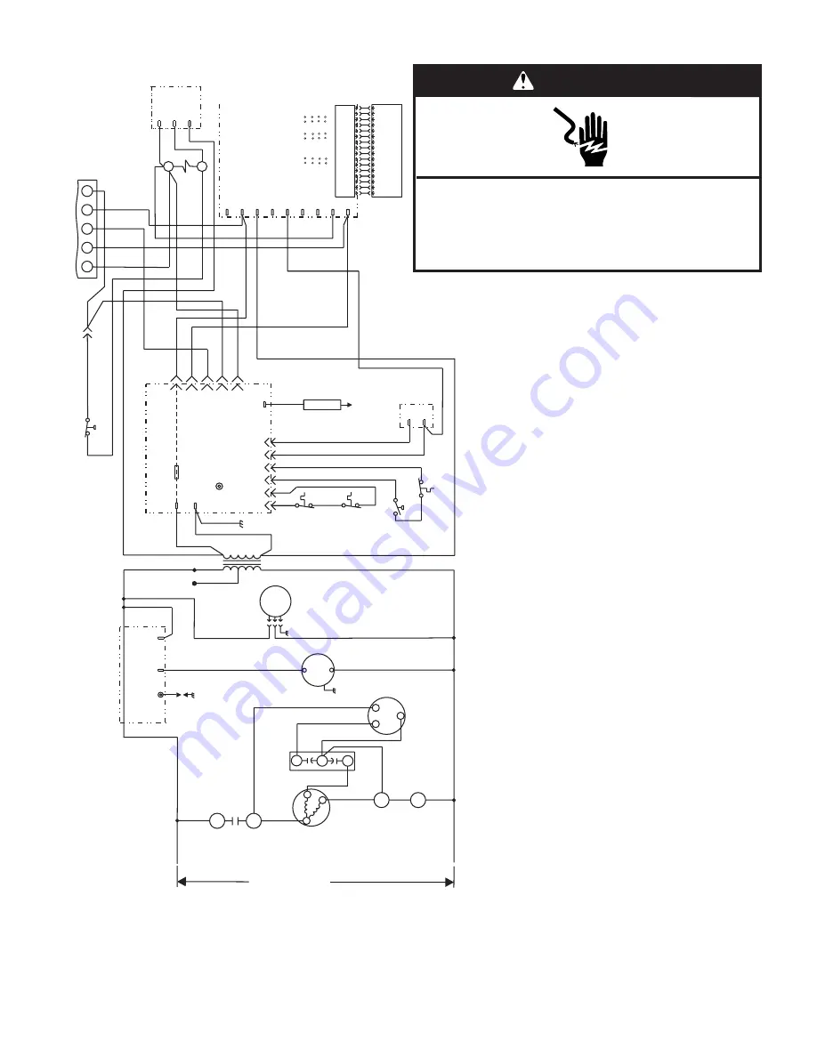
Wiring Connection Diagram—Single Phase, Variable-Speed
208/230V-1-60
1
2
3
4
5
6
7
8
9
10
11
12
13
14
15
16
1
2
3
4
5
6
7
8
9
10
11
12
13
14
15
16
Y
G
W1
R
C
Y
G
W
R
C
BU
G
Y
W
R
Y
R
C
Comfort
Alert
G
Y1
Y2
O
W1
EM
C1
R
HUM
Indoor Blower
M
otor
ICM Board
BU
R
24V
A
C
1
625
4
3
Flame
Flame
Sense
GY
BR
BU
OR
R
Y
G
BK
W
PR
BK
G
PR
OR
WT
PR
Main
Limit
Switch
Rollout
Switch
Pressure
Switch
Aux. Limit Switch
(If used)
Gas
Valve
Fuse
Ignition Control
OR
BU
G
BU
Y
R
R
BU
R
Y
Contactor
Thermostat
Y
Y
High Pressure
Switch
(If used)
L1
T1
T2
L2
C
H
F
Condenser
F
an Motor
Compressor
Contactor
Compressor
Contactor
Dual
Capacitor
Compressor
Transformer
C
S
R
L1
CMB
BL
WR
Spark
Comb.
Air
Blower
Ignition Control
BK
BK
W
L2
L1
BK
BR
PR
R
R
BK
208V
240V
24V
Indoor
Blower
Motor
5 4 3
See
Blower Speed
Chart
BK
S4
S1
K1
A3
GV1
S21
S18
S47
S10
T1
B3
B6
B4
K1-2
C12
B1
K1-1
A3
A54
B3
Ground
BU
Y
A132
ADJUST
HEA
T COOL
NORM
(+)
(-)
(TEST)
A
B
C
D
A
B
C
D
DIA
GNOSTICS
The f
ollo
wing ignition control board LED codes will
indicate nor
mal or abnor
mal oper
ations:
SLO
W FLASH Nor
mal oper
ation, no call f
or heat.
F
AST FLASH Nor
mal oper
ation, call f
or heat.
2 FLASHES System lockout.
3 FLASHES Pressure switch senses incorrect pressure.
.
4 FLASHES Main limit open or rollout switch open.
5 FLASHES Flame sensed and gas valve not energized.
STEAD
Y Inter
nal f
ailure (micro-controller f
ailure;
self chec
k).
LED
Y
E1
Wiring Connection Diagram
Single Stage Heat, Variable Speed, Single Phase
P/N 48107-001
WARNING
Electrical Shock Hazard
Disconnect power before servicing.
Replace all parts and panels before operating.
Failure to do so can result in death or electrical shock.


