6
Convert to Downflow
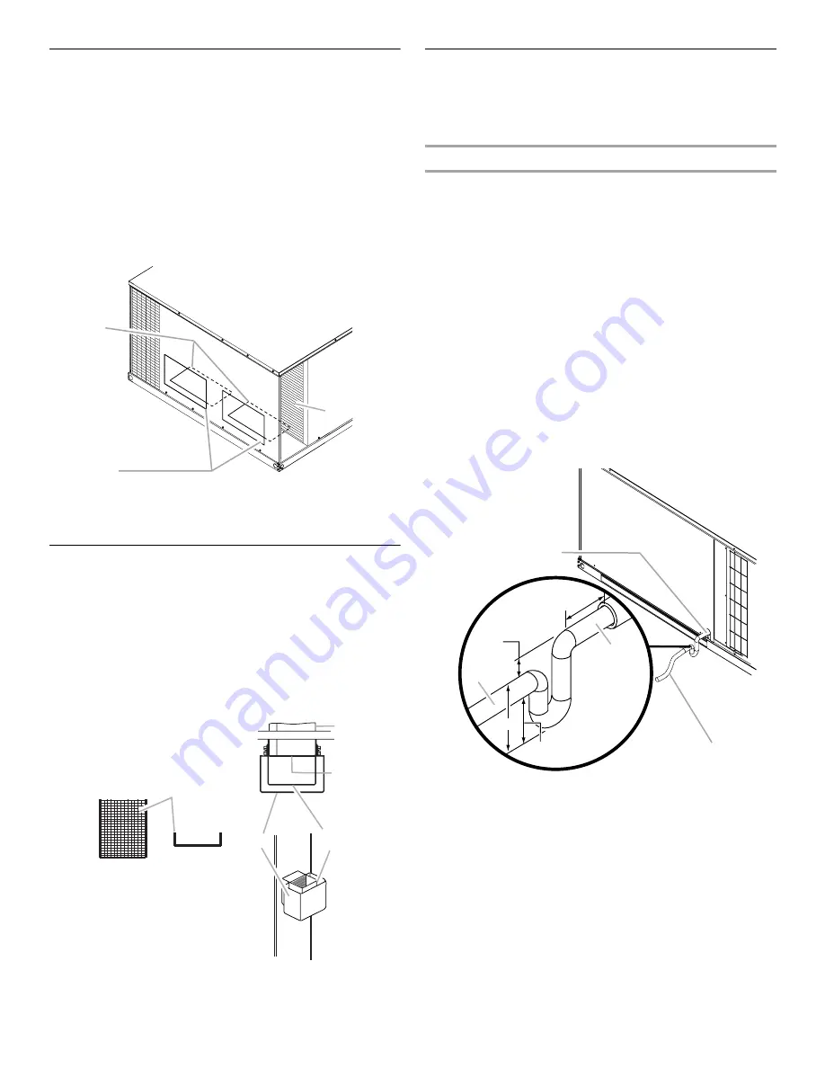
This furnace is factory-built for horizontal airflow applications and
may also be field-converted for downflow use.
To convert to downflow use:
1. Remove the filter access panel.
2. Remove the two downflow duct cover plates (one screw and
tab for each) found in the return and supply air
compartments.
3. Using eight #10 x
³⁄₄
" screws (field supplied), install the
previously removed duct covers on the horizontal return and
supply air openings. Use the pilot holes provided.
4. Reinstall the filter access panel.
Exhaust Vent Assembly
1. Place the screen over the exhaust port.
2. Place the internal vent hood over the exhaust port.
3. Place the outer cover over the internal vent hood and exhaust
port.
4. Align the screw holes in the covers with the holes in the
exhaust port.
5. Attach the covers using the four #10 screws provided.
Connect Condensate Drain
The condensate drain outlet is a
³⁄₄
" threaded PVC fitting located
at the bottom on the side of the furnace. A
³⁄₄
" drain line with trap
must be installed on all applications to avoid accumulation of
condensate under or around the furnace.
Install Condensate Trap
1. Construct the condensate trap from PVC tubing as shown in
“Condensate Trap Construction.”
NOTES:
■
The condensate trap allows a standing column of water of
at least 2" (50 mm).
■
The top of the drain trap inlet must be at least least 1"
(25 mm) above the top of the drain trap outlet.
■
The trap should be installed as close to the furnace as
possible, while still providing proper drainage.
■
For service access, do not block heat exchanger access
panel or the filter access panel with the drain line.
2. Thread the drain assembly into the
³⁄₄
" PVC fitting.
NOTE: Do not glue the threaded fitting so it can be removed
during servicing of unit.
3. Run the drain line to an open drain or other suitable disposal
point.
Condensate Trap Construction
A. Filter access panel
B. Horizontal return and supply air openings
C. Downflow duct cover plates
A. Screen
B. Exhaust port
C. Internal vent hood—slotted side
faces condenser coil
D. Outer cover
C
B
A
To p View
C
F ront View
B
A
A
D
Preformed
A.
³⁄₄
" PVC fitting (threaded) drain condensate connection
B.
³⁄₄
" drain pipes, field provided
C. Drain trap outlet
D. Drain trap inlet
A
B
1" Min.
12" Max.
2" Min.
3" Min.
C
D


