background image

80% GAS FURNACE INSTALLATION INSTRUCTIONS

GAS FURNACE SAFETY

Table of Contents

GAS FURNACE SAFETY................................................................1

INSTALLATION REQUIREMENTS ................................................3

Tools and Parts ............................................................................3
Location Requirements ................................................................4
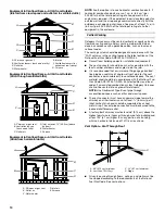
Installation Configurations ...........................................................5
Ductwork Requirements ..............................................................7
Electrical Requirements ...............................................................7
Gas Supply Requirements ...........................................................7
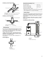
Venting Requirements..................................................................7

INSTALLATION INSTRUCTIONS ..................................................9

Inspect Shipment .........................................................................9
Plan Vent System .........................................................................9
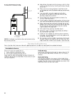
Determine Vent Pipe Direction...................................................12
Connect Venting.........................................................................14
Install Duct Work ........................................................................14

Filter Specifications ....................................................................14
Make Electrical Connections .....................................................15
Make Gas Connections..............................................................16
Check the Furnace Input Rate (if required) ................................17
Adjust the Furnace Input Rate (if required) ................................17
Complete Installation..................................................................18
Shut Down..................................................................................19

SEQUENCE OF OPERATION ......................................................19

Heating .......................................................................................19
Fan On ........................................................................................19
Cooling .......................................................................................20

CONTROLS ...................................................................................20

TROUBLESHOOTING ..................................................................21

ASSISTANCE OR SERVICE .........................................................24

Accessories ................................................................................24

46924B008

Whirlpool

®

 Home Cooling and Heating

14610 Breakers Drive

Jacksonville, FL  32258

Whirlpool

®

 Models 

WFAU, WFAR, WFAT

WFLU, WFLR, WFLT

You can be killed or seriously injured if you don't immediately 
 

You


can be killed or seriously injured if you don't follow 

All safety messages will tell you what the potential hazard is, tell you how to reduce the chance of injury, and tell you what can
happen if the instructions are not followed.

Your safety and the safety of others are very important.

We have provided many important safety messages in this manual and on your appliance. Always read and obey all safety 
messages.

This is the safety alert symbol.

This symbol alerts you to potential hazards that can kill or hurt you and others.

All safety messages will follow the safety alert symbol and either the word “DANGER” or “WARNING.”

These words mean:

follow instructions.

instructions.

DANGER

WARNING

Summary of Contents for WFAR

Page 1: ... 21 ASSISTANCE OR SERVICE 24 Accessories 24 46924B008 Whirlpool Home Cooling and Heating 14610 Breakers Drive Jacksonville FL 32258 Whirlpool Models WFAU WFAR WFAT WFLU WFLR WFLT You can be killed or seriously injured if you don t immediately You can be killed or seriously injured if you don t follow All safety messages will tell you what the potential hazard is tell you how to reduce the chance o...

Page 2: ...ucts carry air circulated by the furnace to areas outside the space containing the furnace the return air shall also be handled by duct s sealed to the furnace casing and terminating outside the space containing the furnace A gas fired furnace for installation in a residential garage must be installed as specified in the Location Requirements section of these instructions The furnace is not to be ...

Page 3: ...n Read and follow the instructions provided with any tools listed here Tools needed Parts needed Check local codes and with gas supplier Check existing gas supply electrical supply and venting and read Ductwork Requirements Electrical Requirements Gas Supply Requirements and Venting Requirements before purchasing parts WARNING Gas leaks cannot always be detected by smell Gas suppliers recommend th...

Page 4: ...ing See Installation Configurations If the furnace is to be installed in an attic or other insulated space it must be kept free and clear of insulating materials Installation Clearances A 2 5 1 cm minimum clearance is required in front for air openings into the combustion chamber All servicing and cleaning of the furnace can be performed from the front If the furnace is installed in a closet or ut...

Page 5: ...ide or bottom return filter rack kit no AFILT524 1 side return or kit no AFILT529 1 bottom return can be used To provide sufficient filter area for installations requiring more than 1 600 CFM nominal air delivery return air will have to be brought through both sides of the furnace or through one side and the bottom or an optional filter rack WAFILTHA7 may be used Installation for Counterflow Downf...

Page 6: ...nstaller must install a sheet metal screw to retain the upper door as shown following in either Position B or D depending on installation configuration Horizontal Installation WFAR and WFLR models Horizontal Installation WFAT and WFLT models Horizontal Installation Suspended WFAR WFLR WFAT and WFLT model furnaces may be installed as suspended units in the horizontal position These furnaces are not...

Page 7: ...pplyRequirements This furnace is equipped for use with Natural gas A conversion kit is required for use with propane To order the correct conversion kit see Accessories Gas supply piping should be installed in accordance with local state and national codes and the regulations of the utility Piping must be of adequate size to avoid undue pressure drop Consult the local utility or gas supplier for c...

Page 8: ...oftening chemicals Deicing salts or chemicals Carbon tetrachloride Halogen type refrigerants Cleaning solvents such as perchloroethylene Printing inks paint removers varnishes etc Cements and glues Antistatic fabric softeners for clothes dryers Masonry acid washing materials Chlorinated laundry products Hydrochloric acid WARNING CARBON MONOXIDE POISONING HAZARD Failure to follow the steps outlined...

Page 9: ...ting of all equipment in the enclosure and not less than 100 sq in 645 cm2 each Equipment in Confined Space All Air from Inside Confined Space Installation Nondirect Venting Air from Outside If air from outside is brought in for combustion the confined space shall be provided with two permanent openings One opening shall be within 12 30 5 cm of the ceiling and one opening within 12 30 5 cm of the ...

Page 10: ... of single wall vent pipe for the vent connector is permissible only in conditioned space The vent material used should be in accordance with the National Fuel Gas Code ANSI Z223 1 NFPA 54 latest edition and local codes Fan assisted combustion system Category I furnaces shall not be vented into single wall metal vents NOTE Use Doublewall Type B vent pipe through unconditioned space such as attics ...

Page 11: ...uilt chimney or vent complying with a recognized standard or a masonry or concrete chimney lined with a lining material acceptable to the authority with jurisdiction NOTE Venting into an unlined masonry chimney or a single wall metal vent is prohibited in all cases A lined masonry chimney may be used Lined Masonry Chimney Venting A 26 gauge galvanized firestop on top of framed opening B Flue pipe ...

Page 12: ...tional Fuel Gas Code or local codes Install all vents in accordance with the vent manufacturer s instructions For unlisted material install in accordance with the National Fuel Gas Code Vent terminals must be installed in accordance with the vent terminals listing or in accordance with the National Fuel Gas Code ANSI Z223 1 NFPA 54 latest edition and local codes DetermineVentPipeDirection The vent...

Page 13: ...e terminal E Clearance to unventilated soffit F Clearance to outside corner G Clearance to inside corner H Clearance to each side of center line extended above meter regulator assembly I Clearance to service regulator vent outlet J Clearance to nonmechanical air supply inlet to building or the combustion air inlet to any other appliance 48 121 9 cm below or to side of opening 12 30 5 cm above open...

Page 14: ...he A coil The A coil should point away from the supply air outlet of the furnace as shown Installation without an Evaporator Coil If a cooling coil is not installed with the furnace then a removable access panel should be provided in the supply plenum for purposes of inspecting the heat exchanger This opening must be accessible when the furnace is installed It must be large enough that the heat ex...

Page 15: ...electrical connection box 5 Using UL listed wire connectors connect the field supply wires to the furnace black to black and white to white 6 Connect ground wire to green ground screw Minimum Filter Requirements Chart Disposable Filters Cleanable Filters Airflow Descriptor Minimum Area sq in cm2 Size in cm Quantity Minimum Area sq in cm2 Size in cm Quantity 09 480 3 096 8 20 x 25 50 8 x 63 5 1 240...

Page 16: ... manual gas shutoff valve IMPORTANT If the inlet gas supply pressure is not within the minimum and maximum range as shown on the rating plate contact your gas supplier 11 Disconnect the pressure gauge from the 3 2 mm NPT inlet pressure tap 12 Replace the inlet pressure tap plug on the gas control valve 13 Turn on the gas supply at the manual gas shutoff valve 14 Test all connections by brushing on...

Page 17: ... the gas control has been in the OFF position for at least 5 minutes before starting the unit 5 Move the gas control to the ON position NOTE This furnace is equipped with an ignition device which automatically lights the burner This furnace cannot be lighted manually Do not try to light the burner by hand 6 Turn on the electrical power to the furnace 7 Set the room thermostat to a point above room...

Page 18: ...in each duct These measurements can be converted to an average to obtain the temperature rise of the whole system 3 If furnace doesn t maintain temperature rise within the range shown on the furnace rating plate adjust the blower speed Manifold Pressure vs Altitude Chart Models WFAR WFAT WFLU WFLR WFLT Only Natural Gas Altitude ft m Heating Value Btu ft3 Manifold Pressure in cm W C Input Factor 2 ...

Page 19: ...me the control energizes the main gas control valve causing the main burners to ignite The hot surface igniter is de energized 3 seconds after the main valve opens If flame is sensed during this time the main valve remains energized and the control starts the 30 second heat blower on delay As heating demand is met the thermostat de energizes the R W circuit The control de energizes the main valve ...

Page 20: ...xist in the burner area This can be caused by a restricted heat exchanger causing main burner flame to roll out into the vestibule area or burner box The rollout switch es must be manually reset by pushing the button on top to restore furnace operation Primary Limit Control This is a normally closed control that opens if abnormally high circulating air temperatures occur It is an automatic reset c...

Page 21: ...sly monitors its own operation and the operation of the system If a system problem occurs a failure code is indicated by the LED on the ignition control See the Failure Codes chart for a description of the flash codes IMPORTANT Do not remove the blower compartment door or turn off the power to the furnace because either action will clear the control s memory of the failure 1 Start the system by se...

Page 22: ...rlock Switch Circulation Blower Not on all models Gas Control Valve Flame Sensor OR MV MV V V V W BR PARK PARK PARK 5A Fuse NEUTRALS Y W Y BK 60 90 120 180 R C W Y G TWIN SW1 60 90 120 180 OR HUM L1 XFMR CONT EAC COOL HEAT V Check codes for proper wiring and circuit protection before installation NOTES 1 Press and release fault code history button to display fault codes To erase codes press and ho...

Page 23: ...eutrals Neutrals Neutrals Neutrals Air Cleaner Heat Cool Blower Motor Neutrals 120 VAC Transformer 24 VAC Pin 3 Pin 2 Pin 12 Pin 9 Pin 6 Pin 5 Pin 11 Pin 1 Rollout Switch Rollout Switch If Used Gas Control Valve Flame Sensor Limit Switch If Used Pressure Switch Aux Limit Switch Aux Limit Switch Condenser Thermostat Pin 8 Pin 4 Pin 7 Pin 10 K5 N N ...

Page 24: ...ne Conversion Kit ALPKT574 2 Natural Gas to Propane Conversion Kit WAFILTHA7 2 Filter Frame Kit AFILT524 1 Side Return Filter Kit AFILT529 1 Bottom Return Filter Kit WABASE511 Combustible Floor Base 14 36 9 cm cabinets WABASE512 Combustible Floor Base 17 44 4 cm cabinets WABASE568 Combustible Floor Base 21 53 4 cm cabinets WABASE569 Combustible Floor Base 24 62 3 cm cabinets 46924B008 2008 All rig...

Reviews: