


11
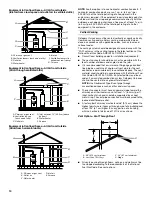
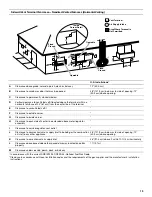
Vent Option—Vent Through Ceiling
Vent Option—Vent Through Floor
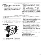
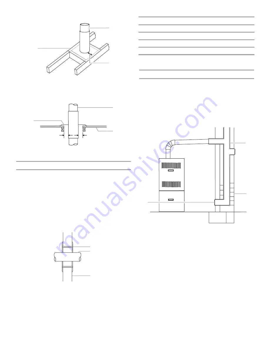
Sidewall Venting
This furnace can be sidewall (horizontally) vented with a listed
sidewall venter such as Field Controls Model SWG-4HD with CK-
43 Control Kit, or Tjernlund Model GPAK-JT. See the Sidewall
Venter Limitations Chart following.
Category I venting classification is maintained when vented in
this manner. The furnace, power venter and control kit (where
applicable) must be installed in accordance with their installation
instructions and all applicable codes.
For horizontal runs of vent pipe, supports are required at 5 ft
(1.5 m) intervals.
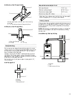
Vent Through Wall
Chimney Options
The furnace must be connected to a factory-built chimney or vent
complying with a recognized standard, or a masonry or concrete
chimney lined with a lining material acceptable to the authority
with jurisdiction.
NOTE: Venting into an unlined masonry chimney or a single wall
metal vent is prohibited in all cases. A lined masonry chimney
may be used.
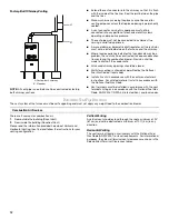
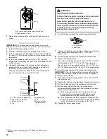
Lined (Masonry) Chimney Venting
A. 26-gauge galvanized firestop on top of framed opening
B. Flue pipe
C. 1" (2.5 cm) clearance between flue pipe and frame
A. Pipe collar (Firestop)
B. Flue pipe
C. Floor
D. 1" (2.5 cm)
A. Thimble
B. Flue pipe
C. Combustible wall
A
B
C
D
D
A
B
C
A
B
C
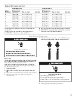
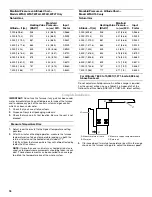
Sidewall Venter Limitations Chart
Vent pipe diameter
4" (10.1 cm)
Minimum vent pipe length
48" (121.9 cm)
Maximum vent pipe length
25 ft* (7.6 m)
Maximum number of 90° elbows
4
*When fewer than 4 elbows are used, maximum vent pipe length
can be increased by 5 ft (1.5 m) per unused elbow.
A. Cleanout
B. Liner
C. Lined masonry chimney
A
B
C


