19
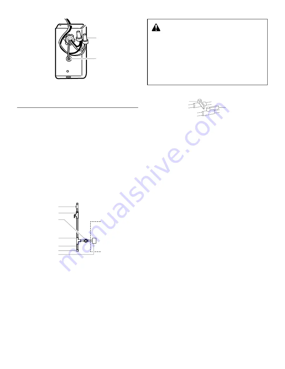
7. Replace the furnace electrical connection box cover and
screw.
Make Gas Connections
IMPORTANT: This furnace requires conversion for use with
propane. To order the correct conversion kit, see “Accessories.”
1. Install the field gas supply as shown.
2. Provide a sediment trap on the outside of the furnace.
3. Install a manual gas shutoff valve in the gas line, outside the
furnace, 5 ft (1.5 m) above the floor, or in accordance with any
local codes.
4. Install a test gauge connection with a
¹⁄₈
" (3.2 mm) NPT
plugged tap immediately upstream of the manual gas shutoff
valve as shown.
5. Connect the gas pipe to the furnace controls providing a
ground joint union as close to the controls as possible to
facilitate removal of controls and manifold.
Pipe-joint compounds suitable for use with Natural and LP
gas must be used. Do not use Teflon
®
tape.
6. Turn off the gas supply at the manual gas shutoff valve.
7. Remove the inlet pressure tap plug on the gas control valve
and connect pressure gauge to the
¹⁄₈
" NPT inlet
pressure tap.
8. Turn on the gas supply at the manual gas shutoff valve.
9. Observe the inlet pressure.
The minimum inlet gas supply pressure is 5" (12.7 cm) W.C.
for Natural gas and 11" (27.9 cm) W.C. for propane gas.
The maximum inlet gas supply pressure is 10
¹⁄₂
" (26.7 cm)
W.C. for Natural gas and 13" (33 cm) W.C. for propane gas.
10. Turn off the gas supply at the manual gas shutoff valve.
IMPORTANT: If the inlet gas supply pressure is not within the
minimum and maximum range as shown on the rating plate,
contact your gas supplier.
11. Disconnect the pressure gauge from the
¹⁄₈
" (3.2 mm) NPT
inlet pressure tap.
12. Replace the inlet pressure tap plug on the gas control valve.
13. Turn on the gas supply at the manual gas shutoff valve.
14. Test all connections by brushing on an approved
noncorrosive leak-detection solution. Bubbles will show a
leak. Correct any leak found.
■
At test pressures greater than
¹⁄₂
psig (3.5 kPa), the
furnace and the manual gas shutoff valve must be
disconnected from the gas supply piping system.
■
At test pressures less than or equal to
¹⁄₂
psig (3.5 kPa),
the furnace must be isolated from the gas supply piping
system by closing the manual gas shutoff valve.
15. Replace the burner access door.
A. Connect white to white and black to black
B. Green ground screw
A.
¹⁄₈
" (3.2 mm) NPT plugged tap
B. Manual gas shutoff valve
C. Ground joint union
D. Tee
E. Sediment trap
F. Cap
G. Gas control valve
(inside furnace)
A
B
®Teflon is a registered trademark of E.I. Dupont de Nemours and
Company.
B
C
D
E
F
G
A
A. Closed valve
B. Open valve
WARNING
FIRE OR EXPLOSION HAZARD
Failure to follow the safety warnings exactly could result
in serious injury, death or property damage.
Never test for gas leaks with an open flame. Use a
commercially available soap solution made specifically
for the detection of leaks to check all connections. A fire
or explosion may result causing property damage,
personal injury or loss of life.
A
B


