16
Make Electrical Connections
Thermostat
Install a room thermostat according to the instructions furnished
with it. Select a location on an inside wall that is not subject to
drafts, direct sunshine, or other heat sources.
Make the low voltage thermostat connections to the blower
control board as indicated on the Wiring Connection Diagram.
Continuous Low Speed Blower
If continuous blower operation on low speed is desired, connect
the low speed motor tap to the CONT (constant) air terminal on
the blower control board. See the Wiring Connection Diagram.
The blower will operate on low speed whenever the main power
is connected to the furnace, except when it operates on heating
or cooling speed during thermostat call for heat or cooling.
NOTE: The constant air terminal is to be connected to the low
speed motor tap only. If a motor is wired for a higher speed, the
increased amp draw could cause the board control to fail and
void the warranty.
1. Disconnect power.
2. Remove the screws from the furnace electrical connection
box.
3. Remove the cover from the furnace electrical connection box.
4. Route the field supply wires to the furnace electrical
connection box.
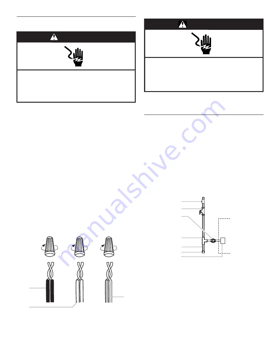
5. Using UL listed wire nuts, connect the field supply wires to
the furnace (black to black and white to white).
6. Using UL listed wire nuts, connect the ground wire to green
pigtail lead.
7. Replace the furnace electrical connection box cover and
screws.
Make Gas Connections
IMPORTANT: This furnace requires conversion for use with
propane. To order the correct conversion kit, see “Accessories.”
1. Install the field gas supply as shown.
2. Provide a drip leg on the outside of the furnace.
3. Install a shutoff valve in the gas line, outside the unit, 5 ft
above the floor, or in accordance with any local codes.
4. Install a test gauge connection with a
¹⁄₈
in. NPT plugged
tapping immediately upstream of the shutoff valve as shown.
5. Connect the gas pipe to the furnace controls providing a
ground joint union as close to the controls as possible to
facilitate removal of controls and manifold.
Pipe-joint compounds suitable for use with L.P. gas must be
used. Do not use Teflon
®
tape.
1. Connect black to black
2. Connect white to white
3. Connect green to ground
WARNING
Electrical Shock Hazard
Disconnect power before servicing.
Replace all parts and panels before operating.
Failure to do so can result in death or electrical shock.
1
2
3
1.
¹⁄₈
in. NPT plugged tapping
2. Shutoff valve
3. Union
4. Tee
5. Drip leg
6. Cap
7. Gas control valve
(inside furnace)
WARNING
Electrical Shock Hazard
Electrically ground furnace.
Connect ground wire to green pigtail lead.
Failure to do so can result in death or electrical shock.
®Teflon is a registered trademark of E.I. Dupont de Nemours and
Company.
2
3
4
5
6
6
7
1


