background image

80% SINGLE-STAGE MULTISPEED GAS FURNACE 

INSTALLATION INSTRUCTIONS

Table of Contents

GAS FURNACE SAFETY................................................................2

INSTALLATION REQUIREMENTS ................................................4

Tools and Parts ............................................................................4
Electrostatic Discharge (ESD) ......................................................4
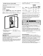
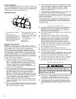
Location Requirements ................................................................4
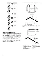
Installation Configurations ...........................................................7
Ductwork Requirements ..............................................................8
Electrical Requirements ...............................................................8
Gas Supply Requirements ...........................................................9
Venting Requirements..................................................................9

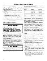
INSTALLATION INSTRUCTIONS ................................................10

Inspect Shipment .......................................................................10
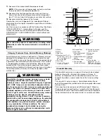
Plan Vent System .......................................................................10
Install Ductwork..........................................................................14
Filter Specifications....................................................................15
Make Electrical Connections .....................................................16
115-Volt Line Connection of Accessories—
Electronic Air Cleaner.................................................................18
Make Gas Connections..............................................................18
Start-Up Procedure and Adjustment .........................................22

Complete Installation..................................................................26
Furnace Shutdown .....................................................................26

SEQUENCE OF OPERATION ......................................................27

Power Up....................................................................................27
Heating Mode—Mode DIP Switch Set to 1 STG Position.........27
Heating Mode—Mode DIP Switch Set to 2 STG Position.........27
Cooling Mode .............................................................................27
Fan Only Mode ...........................................................................27

OPERATIONAL CHECKS.............................................................28

Burner Flame ..............................................................................28
Auxiliary Limit Control ................................................................28
Circulator Blower Speed ............................................................28

MAINTENANCE ............................................................................31

Annual Inspection.......................................................................31
Filters ..........................................................................................31

TROUBLESHOOTING ..................................................................32

Resetting from Lockout..............................................................34

ASSISTANCE OR SERVICE .........................................................36

Accessories ................................................................................36

WPIO-359B

Whirlpool

®

 Home Cooling and Heating

14610 Breakers Drive

Jacksonville, Florida  32258

Whirlpool

®

 Model

WFM18, WFD18

ATTENTION INSTALLATION PERSONNEL

As a professional installer, you have an obligation to know the product better than the customer. This includes all 
safety precautions and related items. Prior to actual installation, thoroughly familiarize yourself with this instruction 
manual. Pay special attention to all safety warnings. Often during installation or repair, it is possible to place 
yourself in a position which is more hazardous than when the unit is in operations. 

Remember, it is your responsibility to install the product safely and to know it well enough to be able to instruct a 
customer in its safe use. Safety is a matter of common sense...a matter of thinking before acting. Most dealers have 
a list of specific good safety practices...follow them.

The precautions listed in this installation manual are intended as supplemental to existing practices. However, if 
there is a direct conflict between existing practices and the content of this manual, the precautions listed here take 
precedence.

Placeholder

Summary of Contents for WFD18

Page 1: ...Resetting from Lockout 34 ASSISTANCE OR SERVICE 36 Accessories 36 WPIO 359B Whirlpool Home Cooling and Heating 14610 Breakers Drive Jacksonville Florida 32258 Whirlpool Model WFM18 WFD18 ATTENTION INSTALLATION PERSONNEL As a professional installer you have an obligation to know the product better than the customer This includes all safety precautions and related items Prior to actual installation ...

Page 2: ... in the Venting Requirements section of these instructions Adequate clearance must be provided around the vent air intake terminals Combustion products must be discharged outdoors Connect this furnace to an approved vent system only as specified in the Venting Requirements section of these instructions Never test for gas leaks with an open flame Use a commercially available soap solution made spec...

Page 3: ... emissions can be re circulated throughout the structure if the furnace or air handler is operating in any mode CO can cause serious illness including permanent brain damage or death DANGER Goodman 43 Should overheating occur or the gas supply fail to shut off turn off the manual gas shutoff valve external to the furnace before turning off the electrical supply WARNING Possible property damage per...

Page 4: ...g furnace installations and servicing to avoid damage to the integrated control module By putting the furnace the control and the person at the same electrostatic potential these steps will help avoid exposing the integrated control module to electrostatic discharge This procedure is applicable to both installed and non installed ungrounded furnaces 1 Disconnect all power to the furnace Do not tou...

Page 5: ...s all local building codes and ordinances In their absence follow the latest edition of the National Fuel Gas Code NFPA 54 ANSI Z223 1 and or CAN CSA B149 Installation Codes local plumbing or waste water codes and other applicable codes A copy of the National Fuel Gas Code NFPA 54 ANSI Z223 1 can be obtained from any of the following American National Standards Institute 1430 Broadway New York NY ...

Page 6: ...othes dryers Masonry acid washing materials If the furnace is used in connection with a cooling unit install the furnace upstream or in parallel with the cooling unit Premature heat exchanger failure will result if the cooling unit is placed ahead of the furnace If the furnace is installed in a residential garage position the furnace so that the burners and ignition source are located not less tha...

Page 7: ... be used to insure safe and proper furnace operation All conversions must be performed by a qualified installer or service agency InstallationConfigurations Horizontal Installation Line contact to framing is permitted when installed in the horizontal configuration Line contact is defined as the portion of the cabinet that is formed by the intersection of the top and side IMPORTANT Accessibility cl...

Page 8: ...al Fuel Gas Code NFPA 54 ANSI Z223 1 and or CAN CSA B149 Installation Codes If resizing is required on any portion of the venting system use the appropriate table in Appendix G in the latest edition of the National Fuel Gas Code ANSI Z223 1 and or CAN CSA B149 Installation Codes DuctworkRequirements Install all conditioned air plenums ducts and air filters if not provided on the furnace in accorda...

Page 9: ...the outdoors or spaces open to the outdoors such as attics or crawl spaces Existing Venting Systems When an existing furnace is removed or replaced the original venting system may no longer be sized to properly vent the attached appliances An improperly sized venting system can result in the spilling of flue products into the living space the formation of condensate leakage etc See the Carbon Mono...

Page 10: ...duced draft blower can be rotated 90 degrees for Category I venting For horizontal installations a 4 10 2 cm single wall pipe can be used to extend the induced draft blower outlet 1 3 cm beyond the furnace cabinet This product is not designed for counterclockwise induced draft blower rotation Vent the furnace in accordance with the National Fuel Gas Code NFPA 54 ANSI Z223 1 latest edition In Canad...

Page 11: ...n on each of the procedures mentioned see the paragraph referenced with each item This inspection is based upon a draft topical report Masonry Chimney Inspection and Relining issued by the Gas Research Institute While not yet finalized we believe this report represents the best information on this subject which is currently available Goodman 68 Never allow the products of combustion including carb...

Page 12: ...0 ft 3 m or Less From Ridge Wall or Parapet Termination More Than 10 ft 3 m From Ridge Wall or Parapet No Yes No Yes Proper chimney termination Check 1 Line terminate with listed vent cap Fix 1 Chimney channel free of solid and liquid fuel appliances Check 2 Change venting arrangements Fix 2 No No No No Yes Yes Yes Yes Rebuild crown Fix 3 and or reline Fix 4 Reline Fix 4 Reline Fix 4 Reline Fix 4 ...

Page 13: ...e caution when doing this as the cut edges of flexible liners may be sharp The surfaces of the liner must be physically sound If gaps or holes are present the metal liner must be removed and replaced Fix 4 Relining Finally confirm that the metal liner is the correct size for the appliances to be installed Use the GAMA tables and rules NOTE If a metal liner is not present a clay tile liner must be ...

Page 14: ... containing chlorine or fluorine a liner of AL 29 4C stainless steel should be used Common sources of chlorine and fluorine compounds include indoor swimming pools and chlorine bleaches paint strippers adhesives paints varnishes sealers waxes which are not yet dried and solvents used during construction and remodeling Various commercial and industrial processes may also be sources of chlorine fluo...

Page 15: ...d air from entering the furnace and if manually operated must be equipped with means to prevent operation of either unit unless the damper is in the full heat or cool position When the furnace is installed without a cooling coil it is recommended that a removable access panel be provided in the outlet air duct This opening shall be accessible when the furnace is installed and shall be of such a si...

Page 16: ...low voltage thermostat connections to the ignition control board as indicated on the Wiring Connection Diagram in Troubleshooting 1 Disconnect power 2 Remove the screw from the furnace electrical connection box 3 Remove the cover from the furnace electrical connection box 4 Route the field supply wires to the furnace electrical connection box 5 Using UL listed wire connectors connect the field sup...

Page 17: ...esistance should measure 10 ohms or less This furnace is equipped with a blower door interlock switch which interrupts unit voltage when the blower door is opened for servicing NOTE Do not defeat this switch 24 Volt Thermostat Wiring NOTE Wire routing must not interfere with circulator blower operation filter removal or routine maintenance Low voltage connections can be made through either the rig...

Page 18: ...onnection The wiring must conform to all local and national codes 5 Connect the COM side of the humidifier to the B C terminal on the furnace control board or to the COM side of the 24VAC transformer NOTE Do not connect 155V humidifier to these terminals MakeGasConnections The furnace rating plate includes the approved furnace gas input rating and gas types The furnace must be equipped to operate ...

Page 19: ...rst 2 threads Use ground joint unions Install a drip leg to trap dirt and moisture before it can enter the gas control valve The drip leg must be a minimum of 3 7 6 cm long Install a NPT pipe plug fitting accessible for test gage connection immediately upstream of the gas supply connection to the furnace Always use a backup wrench when making the connection to the gas control valve to keep it from...

Page 20: ...e only reliable way to detect a propane gas leak Rust can reduce the level of odorant in propane gas Do not rely on your sense of smell Contact a local propane gas supplier about installing a gas detecting warning system All propane gas equipment must conform to the safety standards of the National Board of Fire Underwriters NBFU Manual 58 For satisfactory operation propane gas pressure must be 11...

Page 21: ...r D Continuous 11 W C A D C B Propane Gas Piping Chart I Pipe or Tubing Length ft m Tubing Size O D Type L Nominal Pipe Size Schedule 40 10 3 730 1 700 3 200 5 300 8 300 3 200 7 500 20 6 1 500 1 100 2 200 3 700 5 800 2 200 4 200 30 9 2 400 920 2 000 2 900 4 700 1 800 4 000 40 12 2 370 850 1 700 2 700 4 100 1 600 3 700 50 15 2 330 770 1 500 2 400 3 700 1 500 3 400 60 18 3 300 700 1 300 2 200 3 300 ...

Page 22: ... odor including near the floor 7 If a gas odor is detected following the 5 minute waiting period immediately leave the building and call your gas supplier or the fire department 8 If no gas odor is detected after 5 minutes push the switch to the ON position 9 Replace the door on the front of the furnace 10 Open the manual gas shutoff valve external to the furnace 11 Reconnect the electrical power ...

Page 23: ...e barb fitting from the inlet pressure tap Replace the inlet pressure boss plug and seal with a high quality thread sealer 14 For the White Rodgers 36G22 valve tighten the inlet pressure test screw to seal pressure port clockwise 7 in lb minimum 15 Retest for leaks IMPORTANT Bubbles forming indicate a leak Turn off the gas and repair all leaks immediately 16 Reconnect all electrical power and turn...

Page 24: ...ity 7 Turn off the gas supply to the furnace at the manual shutoff valve 8 Disconnect the manometer 9 Reinstall the plug before turning on the gas supply to the furnace 10 Turn off any unnecessary gas appliances stated in Step 4 Measuring Inlet Gas Pressure Alternate Method Gas Manifold Pressure Measurement and Adjustment A Open to atmosphere B Manometer hose C Outlet pressure boss D High fire reg...

Page 25: ...t R and W contacts to provide a call for heat 20 Retest for leaks IMPORTANT Bubbles forming indicate a leak Turn off the gas and repair all leaks immediately Models Using 2 Stage Gas Control Valves Only small variations in gas pressure should be made by adjusting the gas control valve pressure regulator The manifold pressure must be measured with the burners operating To measure and adjust the man...

Page 26: ...r overheating of the heat exchanger Determine and adjust the temperature rise as follows The temperature rise must be within the range specified on the rating plate or Specification Sheet applicable to your model Please contact your distributor for the applicable Specification Sheet Temperature Rise Measurement Rise Supply air temperature Return air temperature 1 Operate the furnace with burners f...

Page 27: ...fixed 30 second blower on delay Electronic air cleaner terminals are energized with circulator blower Furnace is now operating in low stage heating mode Furnace operates integrated control module monitors safety circuits continuously If low stage delay period expires control will shift operation from low stage heating mode operation to high stage heating mode operation Control will energize circul...

Page 28: ...on requirements from the airflow table in the Product Data Book applicable to your model Please contact your distributor for the applicable product data book 3 Relocate desired motor leads to the circulator blower heat and cool speed terminals on the integrated control module Terminals are identified as LO HEAT HI HEAT and COOL hot If a heating speed and the cooling speed are the same a jumper wir...

Page 29: ...7 43 1 498 45 1 448 46 1 390 1 302 1 222 Med 2 5 1 159 58 1 156 58 1 145 58 1 127 59 1 108 60 1 075 1 033 957 Med Lo 2 0 938 916 916 900 889 865 829 785 Low 1 5 785 766 743 730 709 683 666 604 WFM180904B Medium High 4 0 2 051 1 983 1 895 35 1 812 37 1 725 39 1 627 1 530 1 439 Med 3 5 1 736 38 1 708 39 1 652 40 1 611 41 1 540 43 1 475 1 394 1 307 Med Lo 3 0 1 493 45 1 668 40 1 459 46 1 429 47 1 389...

Page 30: ...181155AXC Medium High 3 0 2 405 35 2 361 36 2 250 38 2 161 39 2 037 42 1 937 1 808 1 689 Med 2 5 1 880 45 1 838 46 1 794 47 1 734 49 1 677 51 1 568 1 510 1 401 Med Lo 2 0 1 659 51 1 630 51 1 587 54 1 537 55 1 492 57 1 445 1 368 1 287 Low 1 5 1 472 58 1 454 59 1 404 61 1 366 62 1 326 64 1 300 1 228 1 139 WFM18 CFM and Temperature Rise vs External Static Pressure Model Heating Speed as Shipped Motor...

Page 31: ...r Size table to ensure proper unit performance To remove filters from an external filter rack in an upright upflow installation follow the directions provided with external filter rack kit Induced Draft and Circulator Blowers The bearings in the induced draft blower and circulator blower motors are permanently lubricated by the manufacturer No further lubrication is required Check motor windings f...

Page 32: ...c part on this furnace Furnace Fails to Operate Properly Review Sequence of Operation and visually inspect the following before troubleshooting Is the integrated ignition blower control board and power to the furnace on Is the blower compartment door securely closed Are the manual shutoff valves in the gas line to the furnace open Are all wiring connections secure Start the system by setting therm...

Page 33: ...lue piping for blockage proper length elbows and termination See Vent Flue Pipe Verify proper induced draft blower performance Check circulator blower speed and performance Correct speed or replace blower if necessary Furnace fails to operate Integrated control module diagnostic LED is flashing 2 flashes 2 flashes Pressure switch circuit is closed Induced draft blower is not operating Induced draf...

Page 34: ...in 24 volt AC control circuits or safety circuits Faulty rollout limit switch Check burners for proper alignment Check flue and air inlet piping for blockage proper length elbows and termination Correct as necessary Check rollout limit switch Replace if necessary Check induced draft blower for proper performance Replace if necessary Tighten or correct wiring connection Repair short in 24 volt AC c...

Page 35: ...t 15 Pin Plug On Some Models Capacitor Circulator Blower BR XFMR 115V 24V Humidifier Integrated Control Module GND XFMR 6 GND 8 MVC 9 MVH 12 MVL 2 Gas Control Valve Induced Draft Blower Pressure Switch C NO C G W R Auxiliary Limit Controls PS 10 PS O 4 HL I 7 HL O 1 To Micro Auto Reset Primary Limit Control RO 2 11 RO 1 5 XFMR 3 Manual Reset Rollout Limit Control s Single Control On Some Models 24...

Page 36: ...rive Jacksonville FL 32258 Please include a daytime phone number in your correspondence Accessories To order accessories contact your Whirlpool Home Cooling and Heating dealer WPIO 359A 2009 All rights reserved Registered Trademark TM Trademark of Whirlpool U S A Manufactured under license by Tradewinds Distributing Company LLC Jacksonville Florida 9 09 Printed in U S A ...

Reviews: