background image

11

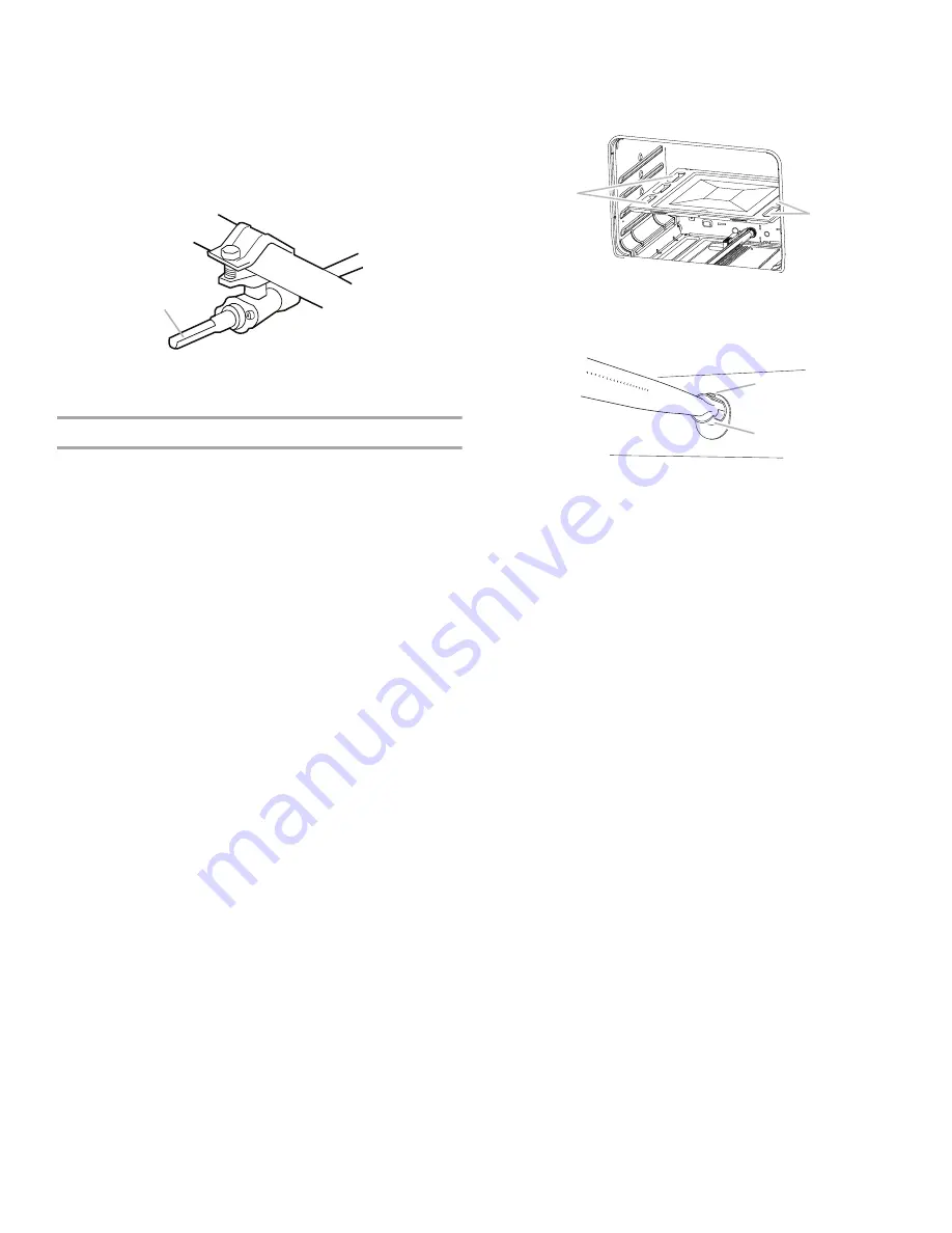
If the low flame needs adjusting:

1.

Turn control knob to the “LOW” setting and remove control 
knob.

2.

Insert a small flat-blade screwdriver into the valve stem. Turn 
the valve adjusting screw to obtain the smallest flame that will 
not go out when the control of a cold burner is quickly turned 
from “HIGH” to “LOW.” Turn right to decrease flame height. 
Turn left to increase flame height. Repeat for other cooktop 
burners as needed.

3.

Replace control knob.

Check Operation of Oven/Broil Burner

Electronic oven control (on some models):

1.

Open broiler door.

2.

Press the “BAKE” pad. 

The “BAKE” indicator will light.

“350” will appear in the display.

3.

Press the START/ENTER pad.

The “TEMP” and “ON” indicators will appear.

The display will show the automatic countdown time 
(10 minutes) needed to preheat the oven for selected 
temperature.

The oven burner should light in 20-40 seconds; this delay 
is normal. The oven valve requires a certain time before it 
will open and allow gas to flow. The oven burner will burn 
until oven temperature has reached 350°F (175°C). After 
20-40 seconds, the oven burner will begin to cycle on and 
off to maintain the 350°F (175°C) temperature.

Broil burner and oven burner are the same burner. Check the broil 
function as follows:

1.

Press the “BROIL” pad.

“525” will appear in the display.

The “BROIL” indicator will light.

2.

Press the START/ENTER pad.

The oven burner should light in 20-40 seconds; this delay 
is normal. The oven valve requires a certain time before it 
will open and allow gas to flow. 

To avoid damaging the hot surface igniter, do not insert any 
object into the openings of the shield that surrounds the 
igniter or clean that area.

3.

Check the oven burner for proper flame. The flame should be 
½" (1.3 cm) long, with inner cone of bluish-green. The outer 
mantle should be dark blue and should be clean and soft in 
character. No yellow tips (not enough air), blowing or lifting 
(too much air) of flame should occur.

If the flame needs adjusting:

1.

Turn the oven off. Wait for the oven burner to cool down.

2.

Open oven door and remove oven racks and oven tray and 
set aside.

3.

Locate the air shutter near the rear wall of oven and loosen 
the shutter screw.

4.

Adjust the air shutter.

5.

Turn the oven back on and check for proper flame. If the 
flame is still not properly adjusted, turn the oven off, wait for 
the oven burner to cool down and repeat Step 4 until flame is 
properly adjusted. 

6.

When the flame has been properly adjusted, turn the oven off, 
wait for the burner to cool down.

7.

Tighten the shutter screw.

8.

Reinstall flame spreader and oven tray. Reinstall the oven 
racks and close oven door.

9.

Close the broiler door.

A. Valve stem

A

A. Oven tray (lift up at area shown to remove)

A. Shutter screw
B. Air shutter

A

A

A

B

Summary of Contents for WFG505M0BB

Page 1: ... et pièces 18 Exigences d emplacement 19 Spécifications électriques 20 Spécifications de l alimentation en gaz 21 INSTRUCTIONS D INSTALLATION 22 Déballage de la cuisinière 22 Installation de la bride antibasculement 22 Raccordement au gaz 23 Vérifier que la bride antibasculement est bien installée et engagée 24 Réglage de l aplomb de la cuisinière 25 Système d allumage électronique 25 Achever l in...

Page 2: ... property damage personal injury or death Do not store or use gasoline or other flammable vapors and liquids in the vicinity of this or any other appliance WHAT TO DO IF YOU SMELL GAS Do not try to light any appliance Do not touch any electrical switch Do not use any phone in your building Immediately call your gas supplier from a neighbor s phone Follow the gas supplier s instructions If you cann...

Page 3: ...stall anti tip bracket to floor or wall per installation instructions Slide range back so rear range foot is engaged in the slot of the anti tip bracket Re engage anti tip bracket if range is moved Do not operate range without anti tip bracket installed and engaged Failure to follow these instructions can result in death or serious burns to children and adults Anti Tip Bracket To verify the anti t...

Page 4: ... be available See Gas Supply Requirements section Contact a qualified floor covering installer to check that the floor covering can withstand at least 200 F 93 C Use an insulated pad or 0 64 cm plywood under range if installing range over carpeting IMPORTANT To avoid damage to your cabinets check with your builder or cabinet supplier to make sure that the materials used will not discolor delaminat...

Page 5: ...his range is equipped with a power supply cord having a 3 prong ground plug To minimize possible shock hazard the cord must be plugged into a grounded 3 prong outlet Electronic ignition systems operate within wide voltage limits but proper grounding and polarity are necessary Check that the outlet provides 120 volt power and is correctly grounded This range is equipped with an electronic ignition ...

Page 6: ...connector If local codes permit a new CSA design certified 4 to 5 ft 122 to 152 4 cm long 1 3 cm or 1 9 cm I D flexible metal appliance connector may be used for connecting range to the gas supply line A 1 3 cm male pipe thread is needed for connection to the female pipe threads of the inlet to the appliance pressure regulator Do not kink or damage the flexible metal tubing when moving the range M...

Page 7: ...the range to support the range when it is laid on its back 5 Using 2 or more people firmly grasp the range and gently lay it on its back on the cardboard corners 6 Pull cardboard bottom firmly to remove then remove foam support 7 Use an adjustable wrench to loosen the leveling legs Adjust the leveling legs to the correct height Leveling legs can be loosened to add up to a maximum of 1 2 5 cm A min...

Page 8: ...B and F in the following illustration 2 Attach one adapter to the gas pressure regulator and the other adapter to the gas shutoff valve Tighten both adapters being certain not to move or turn the gas pressure regulator 3 Use a 2 4 cm combination wrench and an adjustable wrench to attach the flexible connector to the adapters IMPORTANT All connections must be wrench tightened Do not make connection...

Page 9: ...ositioned If burner caps are not properly positioned surface burners will not light Place burners burner caps and grates on the cooktop 6 Plug into a grounded 3 prong outlet VerifyAnti TipBracketIsInstalledand Engaged 1 Place the outside of your foot against the bottom front of the broiler and grasp the lower right or left side of the control panel as shown NOTE If your countertop is mounted with ...

Page 10: ... Place a standard flat rack in oven 2 Place level on the rack and check levelness of the range first side to side then front to back 3 If range is not level pull range forward until rear leveling leg is removed from the anti tip bracket 4 Use a drive ratchet and slip joint pliers to adjust leveling legs up or down until the range is level 5 Push range back into position 6 Check that rear leveling ...

Page 11: ...25 will appear in the display The BROIL indicator will light 2 Press the START ENTER pad The oven burner should light in 20 40 seconds this delay is normal The oven valve requires a certain time before it will open and allow gas to flow To avoid damaging the hot surface igniter do not insert any object into the openings of the shield that surrounds the igniter or clean that area 3 Check the oven b...

Page 12: ... gas supply line shutoff valve is open press the CANCEL button on the oven control panel and contact a qualified technician If you need Assistance or Service Please reference the Assistance or Service section of the Use and Care Guide or the cover of the User Instructions or contact the dealer from whom you purchased your range GAS CONVERSIONS Gas conversions from Natural gas to LP gas or from LP ...

Page 13: ...urn it over and screw it in again 4 Reinstall the cap To Convert Surface Burners 1 Remove burner grate burner caps and burners 2 Locate LP gas orifice spuds for top burners in the bag containing literature included with the range Two LP gas spuds are stamped 88 Yellow Black two are stamped 116 Yellow Orange and one is stamped 70 Yellow White 3 Remove Natural gas orifice spuds using a 7 mm combinat...

Page 14: ...stion operation and burner flame adjustments IMPORTANT You may have to adjust the LOW setting for each cooktop burner Checking for proper cooktop and oven burner flames is very important The small inner cone should have a very distinct blue flame to 0 64 cm to 1 3 cm long The outer cone is not as distinct as the inner cone LP gas flames have a slightly yellow tip 4 Close the broiler door and press...

Page 15: ...rew it in again 4 Reinstall the cap To Convert Surface Burners 1 Remove burner grate burner caps and burners 2 Locate the Natural gas orifice spuds for top burners in the bag containing literature included with the range Two Natural gas spuds are stamped 194 Black White one is stamped 155 Red Brown one is stamped 140 Red White and one is stamped 110 Red Brass 3 Remove the LP gas orifice spuds usin...

Page 16: ...en tray and flame spreader CompleteConversion 1 Refer to the Make Gas Connection section for properly connecting the range to the gas supply 2 Turn the manual shutoff valve in the gas supply line to the open position 3 Refer to the Electronic Ignition System section for proper burner ingestion operation and burner flame adjustments IMPORTANT You may have to adjust the LOW setting for each cooktop ...

Page 17: ...écès Ne pas entreposer ni utiliser de l essence ou d autres vapeurs ou liquides inflammables à proximité de cet appareil ou de tout autre appareil électroménager QUE FAIRE DANS LE CAS D UNE ODEUR DE GAZ Ne pas tenter d allumer un appareil Ne pas toucher à un commutateur électrique Ne pas utiliser le téléphone se trouvant sur les lieux Appeler immédiatement le fournisseur de gaz à partir du télépho...

Page 18: ...uisinière de façon à ce que le pied arrière de la cuisinière se trouve dans la fente de la bride antibasculement Réengager la bride antibasculement si la cuisinière a été déplacée Ne pas faire fonctionner la cuisinière si la bride antibasculement n est pas installée et engagée Le non respect de ces instructions peut causer un décès ou des brûlures graves aux enfants et aux adultes Bride antibascul...

Page 19: ...n Spécifications électriques Une source de gaz adéquate doit être disponible Voir la section Spécifications de l alimentation en gaz Contacter un installateur de revêtement de sol qualifié qui pourra déterminer si le revêtement de sol peut résister à une température d au moins 200 F 93 C Dans le cas de l installation de la cuisinière sur un tapis placer sous la cuisinière une plaque d appui isolée...

Page 20: ...trique le cordon doit être branché dans une prise à 3 alvéoles reliée à la terre Les dispositifs d allumage électronique peuvent fonctionner correctement dans une plage de tension d alimentation étendue mais il est nécessaire de respecter la polarité stipulée et d établir une liaison à la terre adéquate Vérifier que la prise de courant fournit une tension de 120 V et qu elle est correctement relié...

Page 21: ...nt on peut utiliser pour raccorder la cuisinière à la canalisation de gaz un raccord métallique flexible neuf homologation CSA de 4 à 5 pi 122 à 152 4 cm de longueur de diamètre interne de 1 3 cm ou 1 9 cm Un raccord avec filetage mâle de 1 3 cm est nécessaire pour la connexion sur le raccord à filetage femelle à l entrée du détendeur de l appareil Veiller à ne pas déformer écraser endommager le t...

Page 22: ...ment la cuisinière et la déposer délicatement sur sa partie postérieure sur les coins de protection 6 Tirer fermement sur le morceau de carton pour le retirer puis retirer le support en mousse 7 Utiliser une clé à molette pour desserrer les pieds de nivellement Ajuster les pieds de nivellement à la hauteur nécessaire Les pieds de nivellement peuvent être desserrés pour ajouter une hauteur maximale...

Page 23: ...rd flexible voir B et F à l illustration suivante 2 Fixer un raccord d adaptation sur le détendeur et l autre raccord d adaptation sur le robinet d arrêt de la canalisation de gaz Serrer les deux raccords d adaptation 3 À l aide d une clé mixte de 2 4 cm et d une clé à mollette visser le raccord flexible sur les raccords d adaptation IMPORTANT Tous les raccords doivent être bien serrés à l aide d ...

Page 24: ... brûleur n est pas correctement placé le brûleur de surface ne peut s allumer Placer les brûleurs les chapeaux de brûleurs et les grilles sur la table de cuisson 6 Brancher sur une prise à 3 alvéoles reliée à la terre Vérifierquelabrideantibasculementest bieninstalléeetengagée 1 Placer l extérieur du pied contre la partie inférieure avant du gril et saisir le côté inférieur droit ou gauche du tabl...

Page 25: ...ur que le pied de nivellement arrière se dégage de la bride antibasculement 4 Utiliser une clé à cliquet de et une pince multiprise pour régler les pieds de nivellement vers le haut ou vers le bas jusqu à ce que la cuisinière soit d aplomb 5 Repousser la cuisinière pour la remettre en place 6 Vérifier que le pied de nivellement arrière est engagé dans la bride antibasculement REMARQUE La cuisinièr...

Page 26: ...amme doit être de 1 3 cm de longueur avec un cône interne bleu vert La partie externe doit être bleu foncé et doit avoir une apparence propre et lisse Il ne doit y avoir ni pointes jaunes pas assez d air ni souffle ou soulèvement de la flamme trop d air Si la flamme basse doit être réglée 1 Éteindre le four Attendre que le brûleur du four ait refroidi 2 Ouvrir la porte du four et retirer les grill...

Page 27: ...ifié Conversionpourl alimentationaupropane 1 Placer le robinet d arrêt manuel à la position fermée 2 Débrancher la cuisinière ou déconnecter la source de courant électrique AVERTISSEMENT Risque d explosion Utiliser une canalisation neuve d arrivée de gaz approuvée par la CSA International Installer un robinet d arrêt Bien serrer chaque organe de connexion de la canalisation de gaz En cas de connex...

Page 28: ...leurs de surface 1 Ôter la grille du brûleur les chapeaux de brûleurs et les brûleurs 2 Chercher les gicleurs pour gaz propane pour les brûleurs supérieurs dans le sachet de documentation fourni avec la cuisinière Deux gicleurs pour gaz propane portent la mention 88 jaune noir deux la mention 116 jaune orange et un la mention 70 jaune blanc 3 Ôter les gicleurs de brûleur pour gaz naturel à l aide ...

Page 29: ...la plaque du four et le répartiteur de flammes Terminerlaconversion 1 Pour le raccordement correct de la cuisinière à l alimentation en gaz se reporter à la section Raccordement au gaz 2 Tourner le robinet d arrêt de gaz manuel de la canalisation à la position d ouverture 3 Pour l allumage du brûleur l utilisation et le réglage des flammes sur le brûleur se reporter à la section Système d allumage...

Page 30: ... 194 noir blanc un la mention 155 rouge marron un autre la mention 140 rouge blanc et un dernier la mention 110 rouge laiton 3 Ôter les gicleurs de brûleur pour gaz propane à l aide d une clé mixte de 7 mm A Canalisation d alimentation en gaz B Robinet d arrêt manuel à la position fermée C Vers la cuisinière A Détendeur Risque de basculement Un enfant ou une personne adulte peut faire basculer la ...

Page 31: ...tre en place les grilles du four la plaque du four et le répartiteur de flammes Terminerlaconversion 1 Pour le raccordement correct de la cuisinière à l alimentation en gaz se reporter à la section Raccordement au gaz 2 Tourner le robinet d arrêt de gaz manuel de la canalisation à la position d ouverture 3 Pour l allumage du brûleur l utilisation et le réglage des flammes sur le brûleur se reporte...

Page 32: ...W10616596E 2015 All rights reserved Used under license in Canada Tous droits réservés Utilisé sous licence au Canada 8 15 ...

Reviews: