10
Vertical Venting
Category I furnaces must be vented vertically or nearly vertically.
Common venting and multistory venting are permitted when
done in accordance with applicable codes, such as local and
national codes.
The venting system should be designed in accordance with the
“FAN” columns in the venting tables in the latest editions of the
National Fuel Gas Code, ANSI Z223.1/NFPA 54.
■
Consult local building codes for installation requirements.
■
The vent connector should be as short as possible with the
least number of elbows and angles to do the job.
■
It is recommended that a minimum of 26 gauge galvanized
flue pipe be used. Use of single-wall vent pipe for the vent
connector is permissible only in conditioned space. The vent
material used should be in accordance with the National Fuel
Gas Code, ANSI Z223.1/NFPA 54 (latest edition) and local
codes. Fan-assisted combustion system Category I furnaces
shall not be vented into single wall metal vents.
NOTE: Use Doublewall Type B vent pipe through
unconditioned space such as attics and crawl spaces.
■
The vent connector must have an upward slope toward the
chimney on all horizontal runs of at least
¹⁄₄
" per ft of
horizontal run and should be supported by a sheet metal
strap. The vent pipe connection must be secured to the
induced draft blower outlet.
■
All vents passing through floors, ceilings, and walls must be
fire stopped according to the requirements of the National
Fuel Gas Code. See vent options.
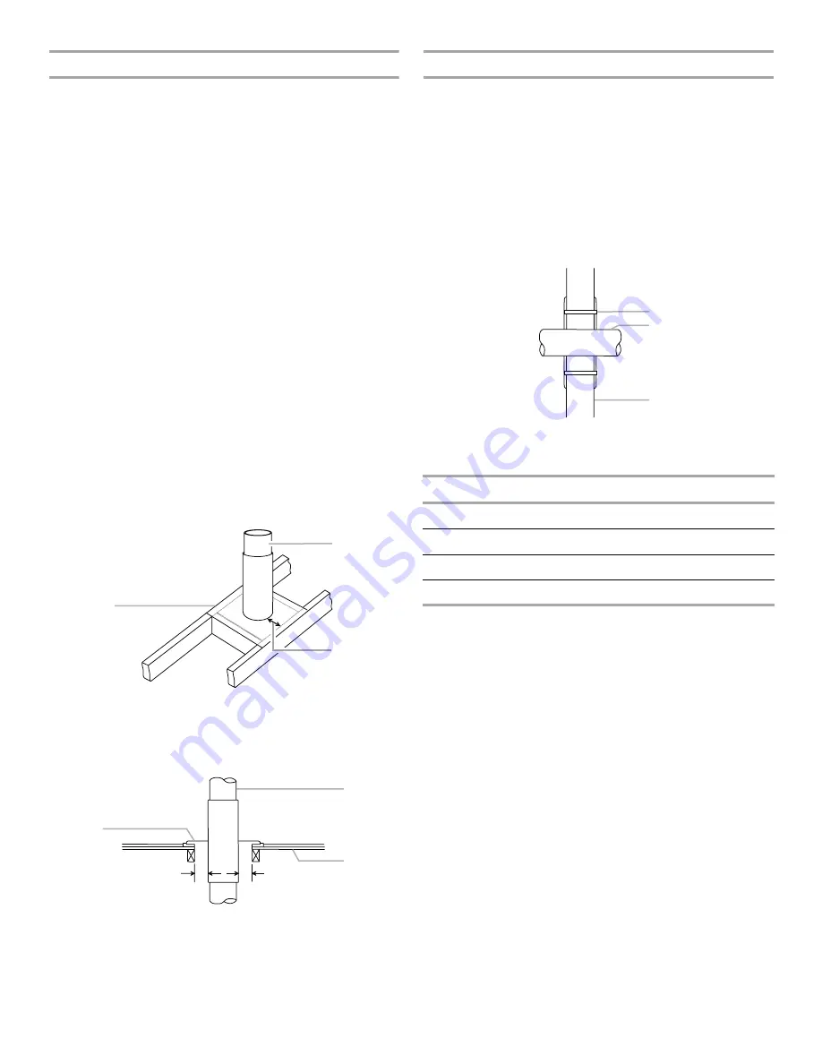
Vent Option—Vent Through Ceiling
Vent Option—Vent Through Floor
Sidewall Venting
This furnace can be sidewall (horizontally) vented with a listed
sidewall venter such as Field Controls Model SWG-4HD with CK-
43 Control Kit, or Tjernlund Model GPAK-JT. See the Sidewall
Venter Limitations Chart following.
Category I venting classification is maintained when vented in
this manner. The furnace, power venter and control kit (where
applicable) must be installed in accordance with their installation
instructions and all applicable codes.
For horizontal runs of vent pipe, supports are required at 5 ft
intervals.
Vent Through Wall
A. 26 gauge galvanized firestop on top of framed opening
B. Flue pipe
C. 1" clearance between flue pipe and frame
A. Pipe collar (firestop)
B. Flue pipe
C. Floor
A
B
C
1"
1"
A
B
C
A. Thimble
B. Flue pipe
C. Combustible wall
Sidewall Venter Limitations Chart
Vent pipe diameter
4"
Minimum vent pipe length
4 ft
Maximum vent pipe length
25 ft*
Maximum number of 90° elbows
4
*When fewer than 4 elbows are used, maximum vent pipe
length can be increased by 5 ft per unused elbow.
A
B
C
Summary of Contents for WGFBLT
Page 23: ...23 Wiring Schematic DRAIN LOW ...
Page 25: ...25 ...
Page 26: ...26 Notes ...
Page 27: ...27 Notes ...


