21
Motor Speed Adjustment
Each WMAHV blower motor has been preprogrammed for
operation at 4 distinct airflow levels when operating in cooling/
heat pump mode or electric heat mode. These 4 distinct levels
may also be adjusted slightly lower or higher if desired.
The adjustment between levels and the trim adjustments are
made by changing the DIP switch(s) either to an OFF or ON
position.
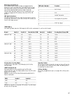
DIP Switch Functions
The WMAHV blower motor has an electronic control that contains
an 8-position DIP switch. The functions of these DIP switches are
shown in the following chart.
CFM Delivery
The following table shows the CFM output for DIP switch combinations 1 and 2, and for 5 and 6.
Thermostat—Fan Only Mode
During Fan Only Operations, the CFM output is 30% of the
cooling setting.
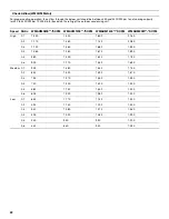
CFM Trim Adjustment
Minor adjustments can be made through the DIP switch
combination of 7 and 8. The following table shows the DIP switch
position for this feature.
NOTE: The airflow will not make the decreasing adjustment in
Electric Heat mode.
NOTE: If no adjustment is required, DIP switches 7 and 8 should
be left in the OFF position.
Humidity Control
When using a humidistat (normally closed), cut jumper PJ6 on the
control board. The humidistat will only affect the cooling airflow
by adjusting the airflow to 85%.
2-Stage Heating
When using staged electric heat, cut jumper PJ4 on the control
board.
DIP Switch Number
Function
1
Electric Heat
2
3
N/A
4
Indoor Thermostat
5
Cooling/Heat Pump CFM
6
7
CFM Trim Adjust
8
Model
Switch 1
Switch 2
Electric Heat CFM
Switch 5
Switch 6
Cooling/Heat Pump CFM
WMAHV 1200
Off
Off
1,200
Off
Off
1,200
On
Off
1,000
On
Off
1,000
Off
On
800
Off
On
800
On
On
600
On
On
600
WMAHV 1600
Off
Off
1,600
Off
Off
1,600
On
Off
1,400
On
Off
1,400
Off
On
1,200
Off
On
1,200
On
On
1,000
On
On
1,000
WMAHV 2000
Off
Off
1,900
Off
Off
2,000
On
Off
1,600
On
Off
1,800
Off
On
1,400
Off
On
1,600
On
On
1,200
On
On
1,200
CFM
Switch 7
Switch 8
+10%
On
Off
-15%
Off
On

