5
INSTALLATION INSTRUCTIONS
Inspect Shipment
The air handler is completely factory assembled, and all
components are performance tested. Each unit consists of a
blower assembly and controls in an insulated, galvanized factory-
finished enclosure. Knockouts are provided for electrical wiring
entrance.
■
Check the unit rating plate to confirm specifications are as
ordered.
■
Upon receipt of equipment, inspect it for possible shipping
damage. Be sure to examine the unit inside the carton if the
carton is damaged.
■
If damage is found, it should be noted on the carrier’s freight
bill. Damage claims should be filed with the carrier
immediately. Claims of shortages should be filed with the
seller within 5 days.
NOTE: If any damages are discovered and reported to the carrier,
do not install the unit as your claim may be denied.
Install Ductwork
IMPORTANT:
■
Install the ductwork in accordance with NFPA 90B Standard
for the Installation of Warm Air Heating and Air-Conditioning
Sytems (latest edition) and any local codes.
■
Connect the supply air duct to the flange on top of the unit. If
an isolation connector is used, it must be nonflammable.
■
A return air duct system is recommended. If the unit is
installed in a confined space or closet, the entire duct cross
sectional area must meet the minimum return air free area.
Install Blower—Cased Evaporator Coil
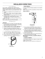
1. Secure the coil and blower together with the 2 connector
plates and screws supplied in the blower bag assembly.
2. Use 1 connector plate and 6 screws on each side of the unit.
3. If accessory electric heat is to be added, install now
according to the instructions shipped with the heater kit.
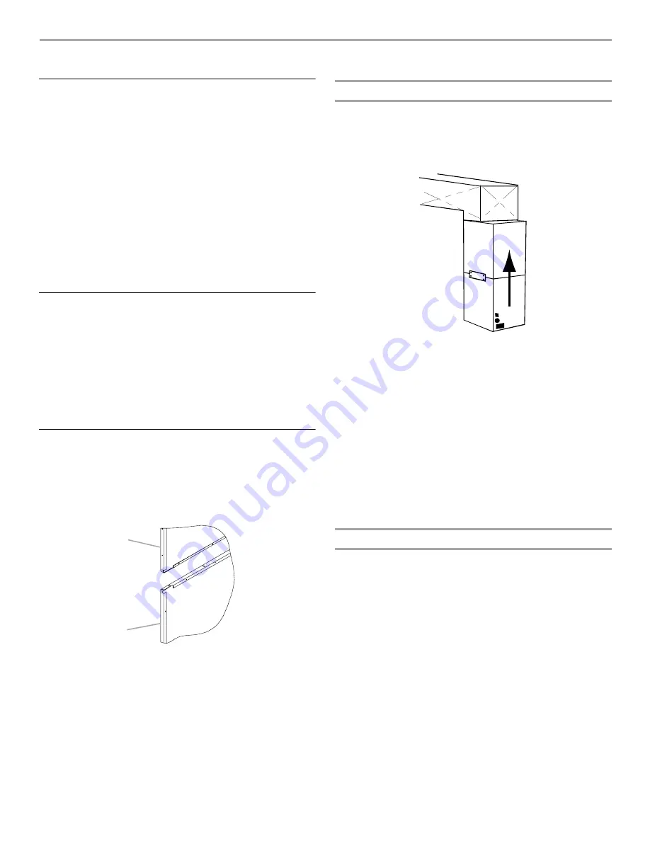
Upflow Installation
For upflow installations, the blower cabinet must sit on top of the
coil cabinet.
NOTE: All panels should be in place before installing the cabinet.
Upflow Installation
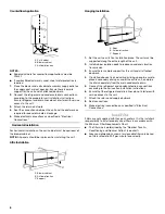
1. Place the blower and coil cabinet assembly upright on the
return duct or duct opening. Ensure that there is ample
support for the cabinet assembly and all attached ductwork.
2. Connect the refrigerant and condensate drain connections
according to the evaporator coil installation instructions.
Ensure that the refrigerant and drain lines do not interfere with
service access to the unit.
3. Attach the supply ductwork.
4. Seal the connections between the unit and the ductwork as
required to reduce/eliminate air leakage.
Make electrical connections as specified in “Electrical
Connections.”
Counterflow Installation
For counterflow installations, the evaporator coil cabinet must sit
on top of the blower cabinet.
NOTE: All panels should be in place when installing the unit.
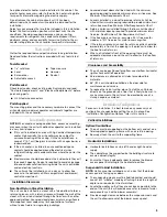
A. Top cabinet
B. Bottom cabinet
A
B
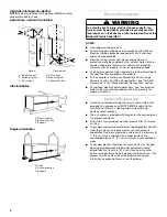
A. Blower cabinet
B. Airflow direction
C. Coil cabinet
A
B
C


