background image


OPERATION 

16


W-GV/2, W-GV/3, W-GV/3+, W-GV 8, W-GV 10 and W-GV 15 — June 2017 — EN


4


OPERATION 

4.1 

GENERAL 

The genverter is operational after full installation and filling up 
with  fuel,  engine  lubricating  oil  and  cooling  liquid,  connecting 
the battery and connecting the digital remote control panel. 

4.2 

PROGRAMMABLE SPEED 

At the time of commissioning, the engine rpm are set to meet 
the output requirements of the installation. 

4.3 

OPERATING INSTRUCTIONS 

4.3.1 

Daily check of oil level 

Be sure to keep the oil level between upper and lower limits of 
the  oil  gauge.  Too  much  oil  may  cause  a  drop  in  output  or 
excessive blow-by gas, while too little oil may seize the engine's 
rotating and sliding parts. 

Procedure

1


Check  the  engine  oil  level  before  starting  or  more  than  5 
minutes after stopping the engine. 

2


Remove  the  oil  dipstick,  wipe  it  clean  and  reinsert  it.  
Take  the  dipstick  out  again,  check  the  oil  level  gauge  and 
reinsert the dipstick. 


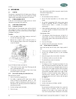
Figure 9: Oil dipstick (similar on all models)


3


If the oil level is too low, remove the oil filler plug, and add 
new oil to the prescribed level.  

4


After adding oil, allow the oil to come down to the oil pan 
before checking the oil level again. 

4.3.2 

Summarized operating instructions (daily use) 

Routine "pre-start" checks: 

1


Check oil level and cooling liquid level. 

2


For  systems  incorporating  PMG:  power  source  selector 
switch  (off/shore  power/generator  power)  in  “off” 
position,  or  switch  of  all  consumers  in  the  usual  way.  If  a 
Whisper Switch of Transfer System Switch is installed, this 
operates automatically. 

3


Switch on battery switch (if installed). 

4


Fuel valve: open. 

Starting: 

Push the start button and hold for a second to initiate the fully 
automatic starting procedure. 

In operation checks: 

1


Check for abnormal noise or vibration 

2


Check  the  output  parameters  on  the  remote  control 
display 

3


For  systems  incorporating  PMG:  switch  power  source 
selector  to  “generator”  position.  If  a  Whisper  Switch  of 
Transfer  System  Switch  is  installed,  this  operates 
automatically.  

4


Before loading the generating set up to its maximum, have 
it run warm. Continuous load should be restricted to 70 % 
of maximum load.  

Stopping the genverter: 

1


If  the  genverter  has  been  running  under  full  load  for  a 
longer  period,  do  not  shut  it  down  abruptly.  Reduce  the 
electrical load to about 30% of the rated load and let it run 
for around 5 min. 

2


Press the STOP button. 

3


Switch to another AC power source, if available 

4.3.3 

Extended operating instructions 

Check  when  starting  the  first  time  or  after  a  longer  period  of 
rest: 

1


If there is any damage caused by transport or installation. 

2


Check  if  the  installation  conforms  to  the  installation 
instructions. 

3


Ensure the engine is free to turn without obstruction. 

4


Check all hoses and hose connections for leaks. 

5


Check all cables and terminal connections. 

Routine "pre-start" checks: 

1


Check  engine  oil  level.  The  genverter  switches  off  in  the 
event of insufficient oil pressure. Even when the oil level is 
too low, the oil pressure can be high enough not to trip an 
alarm. Do not run the engine with the oil below the lowest 
mark,  because  a  smaller  volume  of  oil  will  become 
contaminated  considerably  quicker  than  a  larger  volume. 
Moreover,  a  low  level  may  affect  cooling.  Therefore,  we 
recommend  daily  oil-checks.  Check  oil  level  prior  to 
starting  the  engine  or  at  least  5  minutes  after  the  engine 
has stopped. 

2


Check for leakages. 

3


Switch off all devices. 

4


Switch on the battery switch (when installed). 

Starting the genverter: 

By pushing the start button and holding it for a second, the 
electric  system  is  activated.  You  can  monitor  the 
procedure  on  the  display  of  the  remote  control  panel. 
First,  the  fuel  pump  will  prime  the  fuel  for  a  few  seconds 

Summary of Contents for W-GV 10

Page 1: ...SER S MANUAL W GV 2 W GV 3 W GV 3 W GV 8 W GV 10 and W GV 15 genverters for mobile use WHISPERPOWER BV Kelvinlaan 82 9207 JB Drachten Netherlands Tel 31 512 571550 Fax 31 512 571599 www whisperpower com Art nr 40200981 ...

Page 2: ...0 8 2 4 2 W GV 3 and W GV 15 9 3 TECHNICAL INFORMATION 10 3 1 Explanation of functional parts 10 3 1 1 Control system 10 3 1 2 AC Permanent Magnet Alternator 10 3 1 3 Engine 10 3 1 4 Starter battery charging 10 3 1 5 Alarms and shut down 10 3 1 6 Control 10 3 1 7 Remote control panel 10 3 1 8 Load indicator 10 3 1 9 Fuel 11 3 1 10 Bio diesel 11 3 1 11 Lubricating oil 11 3 1 12 Cooling liquid 11 3 ...

Page 3: ...lter element 20 5 4 9 Checking hoses and electrical connections 20 5 4 10 Servicing after 800 hours and beyond 20 5 5 Putting out of service 20 6 TROUBLESHOOTING 21 6 1 General 21 6 1 1 Failure codes 21 6 2 Alternator electrical faults 21 6 2 1 Troubleshooting table for alternator 22 6 2 Engine faults 22 6 2 1 General 22 6 2 2 Troubleshooting table for engine 22 6 2 3 Warnings 25 6 2 4 Service add...

Page 4: ...general conditions of delivery as registered with the Chamber of Commerce and Industries for the North of the Netherlands number 01120025 and are available on request The guarantee period is two years limited to 1000 running hours Guarantee does not cover failures caused by misuse neglect or faulty installation 1 4 LIABILITY WhisperPower does not accept responsibility for damage injuries or casual...

Page 5: ...ctions or procedures which if not strictly observed may result in damage or destruction of equipment severe personal injury or loss of life WARNING This symbol indicates that a potential hazard exists caused by moving parts and draws attention to special warnings instructions or procedures which if not strictly observed may result in severe personal injury or loss of life WARNING This danger symbo...

Page 6: ... changes in this manual 2 1 8 Fire and explosion Fuels can be flammable Proper handling limits the risk of fire and explosion WARNING Never use the M GV4 Piccolo in situations where there is danger of gas or dust explosion or potentially flammable products Avoid refilling the fuel tank while the engine is running When oil or fuel is leaking do not use the GV4 Scalino Hydrogen gas possibly generate...

Page 7: ...ncy and comfort All cables and hoses are guided through the capsule s sides 2 3 3 Control The Digital Control system of the Genverter is based on microprocessor technology Several operating modes and automatic start stop functions can be programmed and monitored refer to Digital Diesel Control user s manual All functions can be set from the remote control panel which comes as standard with the Gen...

Page 8: ...ck 2 oil filter 3 fuel injection pump 4 stop solenoid 5 fuel line to injector 6 local control panel 7 coolant filler cap 8 oil filler cap 9 thermostat cover coolant temperature sensor behind 10 V belt 11 speed control lever and stop lever behind bar Figure 2 W GV 2 and W GV 8 W GV 3 and W GV 10 service side 1 starter 4 alternator 3 air filter housing 4 Digital Diesel Control 5 Permanent Magnet Alt...

Page 9: ...id 6 fuel injection pump 7 injector 8 coolant filler cap 9 oil filler cap 10 thermostat cover coolant temperature sensor behind 11 V belt 12 oil filter Figure 4 W GV 3 and W GV 15 service side 1 starter 2 oil filter 3 oil pressure switch 4 alternator 5 air filter 6 Permanent Magnet Alternator 7 earth lug 8 exhaust Figure 5 W GV 3 and W GV 15 reverse view 12 11 10 9 8 7 6 5 4 3 2 1 1 2 3 4 6 7 8 5 ...

Page 10: ...ed at 14 4V 3 1 5 Alarms and shut down In the event of malfunctioning this will be indicated by the failure light details will be shown on the display and the engine will be shut down Two parameters are being monitored oil pressure and oil temperature All alarm switches are closed when no malfunction occur A contact is cut in the event of an alarm This means that the Genverter will not work when t...

Page 11: ...engine must be run on heavy duty lubricating oil meeting the requirements of API class CF CF 4 CH 4 CI 4 or CI 4 plus It is recommended to use lubricating oil from WhisperPower or a well known brand It is very important to use the correct oil specification Do not mix different types of oil Higher API class oils and synthetic oils are to be avoided 2 Oil viscosity We recommend 10W40 multi grade oil...

Page 12: ...m 810 565 660mm Dimension mounting h w 340 618 230 618mm 340 680 230 680mm 340 781 230 781mm Dry weight excl sound shield 124kg 141kg 187 kg Dry weight incl sound shield 154kg 171kg 220 kg Color RAL9010 signal white RAL9020 metallic black Engine Engine model Kubota Z482 Kubota D722 Kubota D1105 Emission Regulation Tier 4 EPA Tier 4 EPA Tier 4 EPA Engine performance intermittent SAE J1349 9 32kW 36...

Page 13: ... class H Maximum allowed winding temperature 175 C High voltage test 3000V Regulations and Directives CE conformity EMC directive EMC 2004 108 EC Emission EN 55022 Class A B household light industrial use Harmonics EN 61000 3 2 16A Class A Dips variations flicker EN 61000 4 11 EN6100 3 3 designed to meet Immunity EN 61000 6 2 marine suitable or better LV directive LVD 2006 95 EC Safety EN 60950 Sa...

Page 14: ...el Mitsubishi L2E Mitsubishi L3E Emission Regulation Tier 4 EPA Tier 4 EPA Engine performance intermittent SAEJ1995 11 3kW 3600rpm 9 4kW 3000rpm 16 9kW 3600rpm 14 7kW 3000rpm Engine performance continuous 25 C ambient temperature 9 9kW 3600rpm 8 5kW 3000rpm 15 2kw 3600rpm 13 2kW 3000rpm Number of cylinders 2 3 Displacement 0 635 l 0 952 l Bore stroke 76 70mm 76 70mm Air intake system Naturally asp...

Page 15: ... 16A Class A Dips variations flicker EN 61000 4 11 EN6100 3 3 designed to meet Immunity EN 61000 6 2 marine suitable or better LV directive LVD 2006 95 EC Safety EN 60950 Safety of information technology equipment EN 60335 1 Safety of household and similar electrical appliances Part 1 EN 60335 2 29 Household and similar electrical appliances Safety Particular requirements for battery chargers Vibr...

Page 16: ...noise or vibration 2 Check the output parameters on the remote control display 3 For systems incorporating PMG switch power source selector to generator position If a Whisper Switch of Transfer System Switch is installed this operates automatically 4 Before loading the generating set up to its maximum have it run warm Continuous load should be restricted to 70 of maximum load Stopping the genverte...

Page 17: ...es that need a high current for starting especially electric motors and compressors from a still stand state In order to prolong the genverter s life expectancy the nominal electrical demand of the system should not exceed 70 or the genverter s rated maximum load Please note this when switching on your electrical equipment Nevertheless the genverter is designed so as not to overheat even under ext...

Page 18: ...e to be contacted 5 2 ALTERNATOR The alternator does not require maintenance 5 3 ENGINE 5 3 1 Preliminary instructions The first service on the engine should be carried out after 50 running hours This period also applies after a major overhaul During the first 50 hours the engine should receive special attention Long periods of light or no load running in the first 50 hours may lead to cylinder gl...

Page 19: ...n When ramping up RPM the engine will probably produce some smoke After stabilizing on the right RPM for the load the exhaust should be free from soot Check the electrical connections 5 4 3 Changing engine oil and oil filter cartridge 1 Run the engine until it is on temperature stop it and let it cool down sufficiently to allow safe working 2 Drain oil through the dipstick hole using a vacuum pump...

Page 20: ...e depends on air quality Procedure 1 Unscrew the cover in order to gain access to the filter 2 Clean the foam around the element with compressed air and clean the strainer element 3 Check the air filter and replace it when necessary do not clean the air filter element 4 Put back the cover and retighten the screws 5 4 9 Checking hoses and electrical connections Visually check cooling hoses fuel hos...

Page 21: ...ch are live The alternator generates voltage up to 650 V Remove 3 A fuse from the control panel while working on the Genverter in order to prevent the engine from starting Warning code Problem NO WARNING None no warning was detected LOW STARTBAT Voltage of the start battery BAT1 is below setting NO BAT2 No second battery detected or voltage is below 5V while nominal voltage is set at 12V or 24V ch...

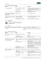
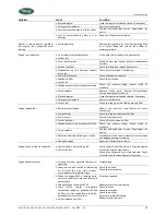
Page 22: ...rdware failure at the engine is detected 6 2 2 Troubleshooting table for engine PROBLEM CAUSE SOLUTION Diesel engine fails to crank no response at all Faulty fuse on the control panel Replace fuse Battery switch off Switch on Battery completely empty Charge or replace battery Diesel engine fails to crank the starter makes clicking noises or the engine cranks very slowly Almost certainly this is a ...

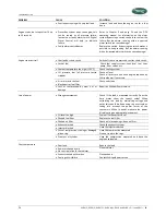
Page 23: ...eck fuel supply system fuel pump and filter Engine speed drops Genverter overloaded Reduce the electrical load switch off some consumers Fuel problem Check fuel supply and clean fuel filter Too much oil Drain oil to proper level Lack of intake air Check air intake clean air filter Choked exhaust system exhaust blocked Check the exhaust piping inspect inside of manifold Faulty actuator Contact Whis...

Page 24: ...ure low oil pressure switch tripped Check oil level Check oil pressure and have engine repaired by WhisperPower if necessary Air or water in the fuel Blocked air or fuel filter Check and clean Loss of compression by wear out or damage Repair by WhisperPower service Loss of power Wrong measurement Check if the load is measured correctly Does the Amp meter show the correct value When calculating the...

Page 25: ...tely if Unusual noise comes from Genverter Exhaust gases suddenly colour dark Engine failure warning light is on 6 2 4 Service address If you cannot correct a problem with the aid of the troubleshooting tables contact your WhisperPower Service Centre or WhisperPower Netherlands for an extended service list Phone INT 31 512 571555 ...

Page 26: ... 40201471 40201471 40201273 40201471 40201471 Pump repair kit B 40201472 40201472 40201274 40201472 40201472 Local control panel PCB 50209142 50209142 50209142 50209142 50209142 Electronic Whisper Control Unit 40401150 40401150 40401150 40401150 40401150 Fuses 10 Amps 50212170 50212170 50212170 50212170 50212170 Fuses 3 Amps 50212154 50212154 50212154 50212154 50212154 Wiring loom complete 4040188...

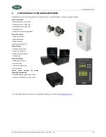
Page 27: ... kits AC and DC belt driven generators Power Conversion Sinewave inverters Inverter chargers Battery chargers Monitoring and control Power Storage AGM and gel batteries Lithium ion batteries Battery related products Solar energy Power Distribution Shore power connect AC distribution Electrolysis prevention DC distribution Hybrid power systems for power generation propulsion 24 48VDC based systems ...

Page 28: ...Inspektionskategorie Catégorie d inspection Hours on indicator Stand Betriebsstundenzähler Etat du compteur d heures Inspected by Prüfer Contrôleur Date Datum Seal stamp full address of responsible WhisperPower Service Center only applicable to items marked Stempel bzw volle Adresse der Whisperpower Servicefirma nur für mit markierten Servicearbeiten Cachet et adresse complète du centre de service...

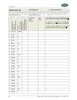
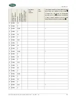
Page 29: ...Service Center only applicable to items marked Stempel bzw volle Adresse der Whisperpower Servicefirma nur für mit markierten Servicearbeiten Cachet et adresse complète du centre de services WhisperPower seulement pour les travaux marqués 19 4400 h 1 2 20 4600 h 1 21 4800 h 1 2 3 4 22 5000 h 1 23 5200 h 1 2 24 5400 h 1 25 5600 h 1 2 3 26 5800 h 1 27 6000 h 1 2 28 6200 h 1 29 6400 h 1 2 3 4 30 6600...

Page 30: ...MAINTENANCE LOG 30 W GV 2 W GV 3 W GV 3 W GV 8 W GV 10 and W GV 15 June 2017 EN ...

Page 31: ... standards Emission standard for residential commercial and light industrial environments 2006 95 EC Low Voltage Directive EN 60950 2000 Safety of information technology equipment 2004 104 EC Automotive EMC Directive 2004 26 EC Non Road Mobile Machinery Exhaust Emissions Directive 2006 42 EC Machinery Directive EN 842 1996 A1 2008 Safety of machinery Visual danger signals General requirements desi...

Page 32: ...Kelvinlaan 82 9207 JB Drachten Netherlands Tel 31 512 571550 Fax 31 512 571599 www whisperpower com info whisperpower com ...

Reviews: