52
WhitakerAudio
(
b
)
– Identify the standoff located at the corner of the board nearby the barrier strip connector.
Remove this standoff; it will be installed on the chassis in a later step.
Locate C3, the three-gang variable capacitor. Note there are connection points on each side of
the device. Note also that on one side of the device there are three screw-adjustable trimmer
capacitors. Set the three adjustment screws so they are tight, and then loosen each by one turn. Set
C3 aside; it will be installed later.
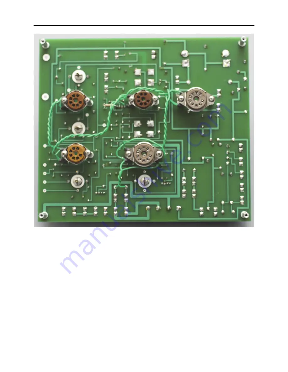
Assembly of the AM tuner PWB has now been completed. The finished board is shown in
Figure 5.3. Check the PWB for proper installation of all components. Look for bad solder
connections or solder splash that might cause a short-circuit.
Set the AM tuner amplifier board aside; it will be installed later.
Summary of Contents for AM/FM Stereo Tuner 2012
Page 1: ...WhitakerAudio AM FM StereoTuner User and Assembly Manual...
Page 11: ...11 AM FM Stereo Tuner Figure 1 1 Schematic diagram of the AM tuner section...
Page 17: ...17 AM FM Stereo Tuner Figure 1 2 Schematic diagram of the FM tuner section...
Page 34: ...34 WhitakerAudio Figure 3 1 Component layout for the AM tuner PWB...
Page 36: ...36 WhitakerAudio Figure 3 3 Component layout for the FM tuner PWB...
Page 69: ...69 AM FM Stereo Tuner Set the FM tuner board aside it will be used later b...
Page 101: ...101 AM FM Stereo Tuner Figure 5 11 Chassis view of the AM FM Stereo Tuner...
Page 159: ...159 AM FM Stereo Tuner...
Page 160: ...WhitakerAudio AM FM StereoTuner...


