background image

3.

 Install the parts as shown in the exploded view, using heavy grease on all internal 

parts. Thread the assembly into the inner leg. Use a 25 mm socket to get the 
stanchion plug started, being carful not to cross thread it into the stanchion.

Rebuilding the Damper Leg Assembly

1.

 Throughly clean all the parts.

2.

 Inspect for obvious signs of damage. Pressurize the damper canister to at least 50 

psi. Test the damper by pushing the shaft down. It should compress and return in a 
controlled manner. Screw the compression adjuster in to insure the damper slows 
when adjusted. At the top of the stroke,  if the damper shaft does not return to 8” 
above the seal head  this indicates the need for damper service. Reinstall the 
greased  spring  Reinstall the washer and bumper after the outer leg is installed.

Reinstalling the Outer Legs

1.

 Apply Slick Honey or other non-lithium based suspension lube to the DU bushings                      

inside the outer leg. Make sure to lube the lower DU bushing which is deep in the 
outer leg. 

2.

 With all parts cleaned and reinstalled with new grease, fit the outer leg over the 

stanchion tube and gently rock and slide the legs until the inner leg slides into the 
bushings. Slide the outer leg all the way down to the drop out. Check for 
noticeable play between the stanchion tubes and the fork lower. If there is play, 
contact White Brothers for service. 

Reinstalling the Springs and LH Top Cap

1.

 A 10mm wrench will hold the flats on the shaft as you thread the top cap down     

until it stops. Hold the top cap with a 25 mm socket and tighten.

2.

 Thread the top cap into the outer leg and tighten. 

Note: A little more than hand 

tight is all that is necessary, as the upper clamp will hold the top caps tight. 

Reinstalling the RH Top Cap

1.

 Screw the rebound needle in clockwise until it stops then back it out 3 to 4 turns. 

2.

 Install the small spacer under the top cap if you removed it earlier.

3.

 On the damper shaft, install the chrome bottom out spring onto the seal head, 

spring spacer and then the yellow bumper with heavy grease on all parts. The parts 
will be seated the first time the fork bottoms out. 

4.

 Install the top cap onto the damper shaft and tighten. Remove the assembly from 

the vise and thread the top cap into the outer leg and tighten. 

Note: A little more 

than hand tight is all that is necessary, as the upper clamp will hold the top caps 
tight. 

7.

 Readjust the rebound needle to your preferred position.

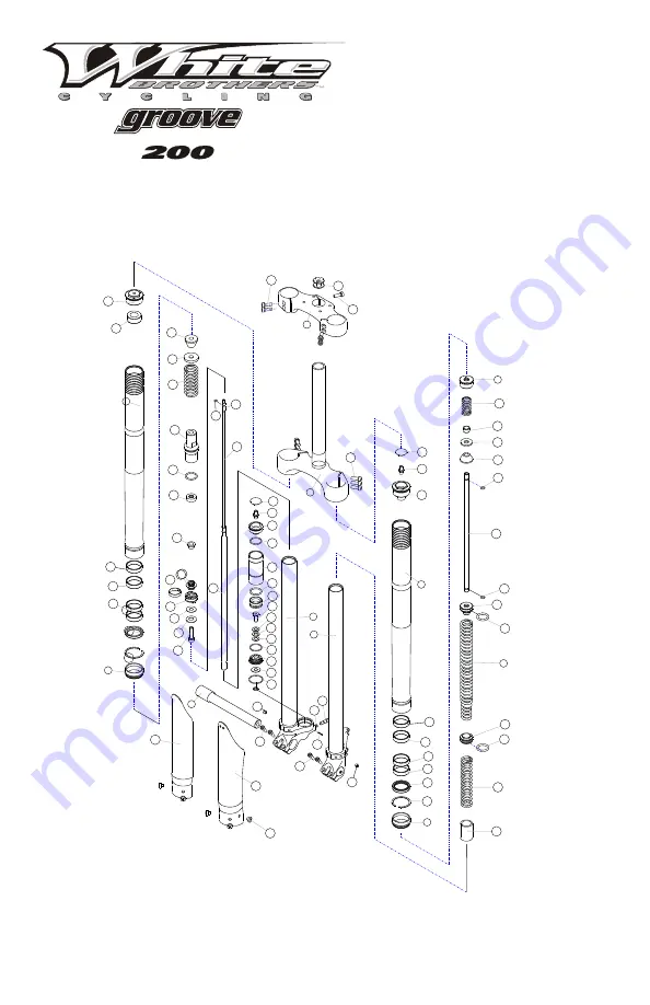
The following is an illustration 

and parts table which gives 

you the exploded view of your 
White Brothers fork. The parts 

table indicates the part 

Page 8

Page 9

22

45

28

29

30

31

32

34

35

36

33

26

27

27

11

23

24

25

21

1

58

58

58

57

56

8

7

50

51

52

54

3

55

54

49

20

10

1

54

2

49

20

48

38

46

43

43

43

41

62

53

53

37

42

44

45

47

9

15

60

18

17

61

14

61

19

16

4

13

19

12

59

58

58

58

57

56

8

65

65

64

58

58

40

5

6

64

63

Summary of Contents for Groove 200

Page 1: ...Mountain Racing Products Inc 580 N Westgate Dr Grand Junction CO 81505 USA 1 970 241 3518 www whitebrotherscycling com A Division Of OWNERS MANUAL ...

Page 2: ...YOUR DEALER OR TO WHITE BROTHERS FOR ACOMPLETE INSPECTION AND NECESSARY REPAIR 4 PERFORM ALL RECOMMENDED MAINTENANCEACCORDING TO THE MAINTENANCE SECTION OF THIS MANUAL FAILURETO PERFORM MAINTENANCE COULD DRASTICALLYREDUCE THE FORK S LIFE PERFORMANCE AND CAUSE YOUR FORKTO BE ASAFETY HAZARD 5 WHITE BROTHERS RECOMMENDS THAT YOU WEAR PROPER SAFETY EQUIPMENT EVERYTIME YOU RIDE INCLUDINGAN APPROVED BICY...

Page 3: ... 1 1 8 threadless steerer tube Check with your frame manufacturer to ensure your bike is designed for a triple clamp fork If not you may void your warranty 1 Remove your old fork from the bicycle Measure the diameter and length of your old fork s steerer tube to ensure that the White Brothers steerer tube is the correct diameter and sufficient length for the installation 2 Remove the crown race fr...

Page 4: ...ompressed and released Warning When installing the wheel or a new tire check for minimum clearance Measure from the highest point on the tire to the under side of the crown There must be 1 8 or 3mm more clearance than the fork s travel to ensure adequate clearance in all riding conditions Any less clearance can cause the tire to hit the crown resulting in serious injury or death The Groove 200 wil...

Page 5: ...ll pack up feel harsh over consecutive bumps while rebound set too fast will cause the fork to top out harshly If the fork is topping out and you have the correct spring for your weight turn the adjuster one turn at a time until the top out stops 2 Compression damping can be changed two ways 1 by adjusting the compression damping screw on the back of the canister on the bottom of the right fork le...

Page 6: ...center Tools needed forservice Quantity Part Number Description 1 WB 97 700 Clamp block 1 SH EDL 04 Suspension Lube 1 9 mm Open End wrench 1 25 mm Socket 1 3mm Allen Wrench 1 25 mm Open End Wrench White Brothers recommends that you consult a tech before performing the following BASIC FORK DISASSEMBLY Removal of the Leg Assemblies 1 Disconnect the front brake and loosen the pinch clamp bolts at the...

Page 7: ...he outer leg Check for noticeable play between the stanchion tube and the outer fork tube If there is play contact White Brothers or a qualified dealer for service Slide the outer leg down to the axle clamp 2 Unscrew the top cap counterclockwise from the shaft by holding the flats on the shaft with an open end wrench Note there is a small spacer under the cap that can fall out 3 Remove plastic was...

Page 8: ...ock and slide the legs until the inner leg slides into the bushings Slide the outer leg all the way down to the drop out Check for noticeable play between the stanchion tubes and the fork lower If there is play contact White Brothers for service Reinstalling the Springs and LH Top Cap 1 A10mm wrench will hold the flats on the shaft as you thread the top cap down until it stops Hold the top cap wit...

Page 9: ...ers fork The parts table indicates the part Page 9 22 45 28 29 30 31 32 34 35 36 33 26 27 27 11 23 24 25 21 1 58 58 58 57 56 8 7 50 51 52 54 3 55 54 49 20 10 1 54 2 49 20 48 38 46 43 43 43 41 62 53 53 37 42 44 45 47 9 15 60 18 17 61 14 61 19 16 4 13 19 12 59 58 58 58 57 56 8 65 65 64 58 58 40 5 6 64 63 ...

Page 10: ... 1409 Shaft Seal 29 1 P2014 Check Valve Guide 30 1 P2015 Check Valve Spring 31 1 P2004 Check Valve 22x12x0 02 32 1 P2012 Piston 33 1 P3000 Piston Band 34 1 P2006 Low Spd Shim 22x8x0 02 35 1 P2005 Belvil Washer 36 1 P4010 Shim Stack Bolt 37 1 P3026 O Ring 024 38 1 P1515 1 Reservoir Can 39 1 P2001B Shim 40 1 29 136 Shim 41 1 P2016 Compression Piston 42 1 P3028 O Ring 021 43 3 29 127 Shim 44 1 P4011 ...

Page 11: ...Page 11 MAINTENANCE LOG Date Service Performed ...

Page 12: ...MAINTENANCE LOG Date Service Performed Page 12 ...

Page 13: ...MAINTENANCE LOG Date Service Performed Page 13 ...

Page 14: ...MAINTENANCE LOG Date Service Performed Page 14 ...

Page 15: ...tered serial numbers located on the back of the right fork stanchion The fork is not warrantied against damage in the appearance of the fork or for modifications not outlined in this manual This warranty does not cover breakage bending or damage that may result from crashes falls or abuse Normal wear i e seals bushings sliders finish etc and tear and damage caused by lack of proper maintenance is ...

Page 16: ...Mountain Racing Products Inc 580 N Westgate Dr Grand Junction CO 81505 USA 1 970 241 3518 www whitebrotherscycling com A Division Of ...

Reviews: