background image

6

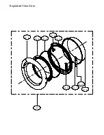
Door Assembly - up to WK1537

4213 092 64901

301160700018

6

Door Assembly - from WK1538

4213 092 69281 

12138200A02721

6.1

Outer Frame

4213 092 64911

301160700053

6.2

Protect Cover

4213 092 64921

301160700057

6.3

Inner Ring Seal

4213 092 64941

302760700005

6.4

Door Plunger - up to WK1537

4213 092 64961

302960700011

6.4

Door Plunger - from WK1538

4213 092 68541

302960700015

6.5

Inner Ring (2 Ribs)  - up to WK1537

4213 092 64951

301160700054

6.5

Inner Ring (No Ribs)  - from WK1538

4213 092 68561

301160700054

6.6

Door Hinge Pedestal

4213 092 64981

301160700058

6.7

Parallel Pin

NOT AVAILABLE

302960700010

6.8

Hinge Support

4213 092 64971

302960700009

6.9

Window Door

4213 092 64931

301160700056

7

Top Cover Assembly

4213 092 65491

301160700015

8

Upper Support

4213 092 65441

301160700012

9

Bottle Assembly

4213 092 65431

301160700069

10

Housing Bottle

4213 092 65451

301160700011

11

Water Bottle Handle And Printing

4213 092 65421

3011608A0038

12

Top Bracket

4213 092 65601

301260700009

13

Bracket Side

4213 092 65461

301260700006

14

Right Top Bracket

4213 092 65471

301260700007

15

Air Inlet Grill

NOT AVAILABLE

301160760146

16

Long Belt

4213 092 65511

302760700001

17

Cover Back

NOT AVAILABLE

301260700012

18

Side Panel

4213 092 65551

301260700008

19

Maintenance Cover

4213 092 65571

301160760145

20

UK Power Cord

4213 092 65501

302460760022

21

Electric Filter

4213 092 65481

302360700001

22

Door Gasket  - up to WK1537

4213 092 65581

301160700007

22

Door Gasket  - from WK1538

4213 092 68551

302760860001

23

Overflow Hose

4213 092 65411

301160700010

24

Drain Hose

4213 092 65331

302760700008

25

Inlet Duct

4213 092 65531

301260700010

www.whiteknightspares.co.uk

www.whiteknightrange.co.uk

Summary of Contents for B96M8W

Page 1: ... Safety Guide Wiring Diagram Exploded Views Parts List September 2016 8kg Condenser Tumble Dryer UK White Knight B96M8W SERVICE MANUAL Note Please read before servicing the unit Any problems contact your service centre ...

Page 2: ... is operating 3 8 Error warning codes 4 1 Disassembly warnings 4 2 Disassembly methods 5 Wiring diagram 6 Exploded view 2 User error checklist please check prior to service Symptoms Check whether The drum does not rotate There is power to the appliance The door is closed The correct program has been selected and the start button has been pressed The dryer gives out abnormal heat The heat exchanger...

Page 3: ...ection diagram P0 Live and neutral P1 Load moisture sensor P2 Motor L heater 700W L P3 Drum light and pump P4 Door switch P5 Heater N motor N P6 Heater 1600W L P7 Water level sensor Inlet thermistor and Exhaust thermistor ...

Page 4: ... Re fit or replace belt NO YES Check if the terminals of P2 are loose Ensure that the terminals are connected correctly NO YES Check the front support wheel for damage Replace the front support wheel including wheel shaft NO YES Check if the capacitor has correct value Insert or replace capacitor and is connected to the loom NO YES Check if the tension spring Install or replace the tension spring ...

Page 5: ...s the ambient temperature higher than 35 C NO YES Check the correct program has been selected Select the correct program NO YES Check if the dryer is overloaded The load placed in the drum must not exceed the maximum load rating stated in the instruction book NO YES Check that the filter is clean Clean the filter NO YES Is the heat exchanger blocked Clean the heat exchanger NO YES Is the Inlet the...

Page 6: ...ble or replace the fan NO YES Is the drum bearing drive shaft damaged Replace the drum assembly NO YES Does either the drainage or overflow Ensure the hoses are positioned correctly pipe rub on the rotating drum 3 6 The dryer produces an abnormal smell when operating YES Is there any sign of deposits on the heater Clean the heater NO YES Is the main drive belt slipping Replace the main drive belt ...

Page 7: ...s and restart the machine E33 Inlet thermistor not functioning correctly Check the inlet thermistor on heater assembly and check associated connections E34 Exhaust thermistor not functioning correctly Check the exhaust thermistor below filter and check associated connections 4 1 Disassembly warnings The mains cable must be disconnected from the power supply when disassembling or repairing the mach...

Page 8: ...screws at the rear of the top cover and slide top cover backwards 2 Remove the bottle 3 Remove 4 screws at the front of the dryer from the control panel and cross brace 4 Remove 2 screws inside the slots on the control panel 5 Remove all of the connections from the back of the PCB ...

Page 9: ...of appliance and left hand side panel screws along top at rear and underneath appliance from the appliance 1 Pull out the drainage hose connector from the pump cover 2 Remove the pump cover s 3 Remove the nut on water level sensor to allow the water level sensor to be removed from the pump cover Unclip the wires 3 Disassembling the door 1 Remove the screws holding the hinge to the front panel Lift...

Page 10: ...er 1 Remove the screws from the rear panel 2 Remove the screws from the air ductwork below the heater 3 Remove the top cover by unscrewing the screws at the back of the appliance 4 Disconnect the loom harness from the RFI filter 5 Disconnect the terminal from the heater connector ...

Page 11: ...r of the appliance removed remove the bracing struts between the front and backpanels Remove the screws which hold the metal backpanel to the plastic base The drum and the backpanel should now come away as one item 2 Remove the main drive belt from the drum subassembly 3 Remove the two screws from the bearing cover 4 Remove the ring seal from the bearing cover ...

Page 12: ...5 Remove the nut with adjustable wrench or similar 6 Remove the drum shaft ring 7 Remove the backpanel from the drum 8 Remove the other two shaft rings ...

Page 13: ...ring Diagram 1 Pump 2 Drum light 3 Door Switch 4 Moisture level sensor 5 Mains cable 6 RFI filter 7 Motor 8 Capacitor 9 Heater 10 Inlet thermistor 11 Water level sensor 12 Exhaust thermistor 6 Exploded View ...

Page 14: ...Exploded View Base ...

Page 15: ...Exploded View Front Support ...

Page 16: ...Exploded View Control Panel Water Bottle ...

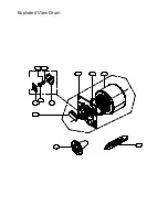
Page 17: ...Exploded View Drum ...

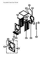
Page 18: ...Exploded View Front Panel ...

Page 19: ...Exploded View Door ...

Page 20: ... 4213 092 65071 302460700013 2 6 Lamp 4213 092 65091 302460700012 2 7 Front Support Assembly 4213 092 65061 301160700037 2 8 2 9 Cover Lamp Seal 4213 092 65081 301160700039 2 10 Lint Filter 4213 092 65051 301160700070 2 11 Wheel Assembly 4213 092 65121 302960860008 2 12 Temperature Sensor 4213 092 65151 302411600802 2 13 Seal Thermistor 4213 092 65141 302760700003 2 14 Nut 4213 092 65741 302560700...

Page 21: ...er Support 4213 092 65441 301160700012 9 Bottle Assembly 4213 092 65431 301160700069 10 Housing Bottle 4213 092 65451 301160700011 11 Water Bottle Handle And Printing 4213 092 65421 3011608A0038 12 Top Bracket 4213 092 65601 301260700009 13 Bracket Side 4213 092 65461 301260700006 14 Right Top Bracket 4213 092 65471 301260700007 15 Air Inlet Grill NOT AVAILABLE 301160760146 16 Long Belt 4213 092 6...

Reviews: