35362-3-1015
Page 17
INSTALLATION (continued)
Attention:
Cold climate installation recommendation: When
installing this unit against a non-insulated exterior wall, the outer
walls should be insulated to conform to applicable codes.
)LQLVKWKHMRLQWEHWZHHQWKH¿UHSODFHDQGZDOOZLWKVHDODQWUDWHG
at 300 degrees F, or tile/stone over the joint.
Vent Runs
,QSODQQLQJWKHLQVWDOODWLRQIRUWKH¿UHSODFHLWLVQHFHVVDU\WRLQVWDOO
certain components before the appliance is completely positioned
and installed. These include the direct vent system, gas piping for
the appliance and the electrical wiring. (If the fan option is used.)
The appliance can be mounted on any of the following surfaces:
$ÀDWKDUGFRPEXVWLEOHEXUQDEOHVXUIDFH
2. A raised wooden platform.
3.
Four corner supports. (Example: Four concrete masonry blocks.)
These supports must be positioned so they contact all four
perimeter edges on the bottom of the unit.
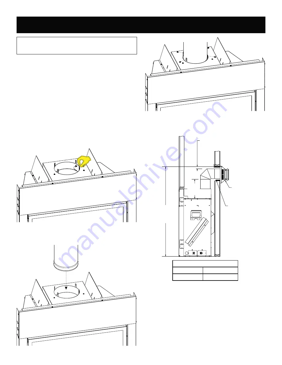
Securing the Vent Pipe to the Fireplace
1. Hand bend the tabs up on the Outer Wrapper Top Assembly
as shown in Figure 20.
Figure 20
,QVHUWWKH¿UVWSLHFHRISLSHDQGVHFXUHZLWKVFUHZVWKURXJK
the tabs and into the pipe.
See Figures 21 and 22.
Figure 21
Figure 22
VERTICAL, 90 DEGREE ELBOW WITH HORIZONTAL
TERMINATION
3” (76mm)
MINIMUM CLEARANCE
TO COMBUSTIBLES
VENT CAP/
THIMBLE
WALL FIRESTOP
“A”
DISTANCE
TO BOTTOM
OF UNIT
12 INCH
RISE
REQUIRED
A DIMENSION (in inches)
DVCX36
57-1/2
DVCX42
57-1/2
Figure 23


