35362-3-1015
Page 28
FRAMING AND FINISHING (continued)
Vertical Firestops
Vertical runs of this system which pass through ceilings require
WKHXVHRI21(FHLOLQJ¿UHVWRSDWWKHKROHLQHDFKFHLOLQJWKURXJK
which the vent passes.
Position a plumb bob directly over the center of the vertical vent
component and mark the ceiling to establish the center point of the
vent. Drill a hole or drive a nail through this center point and check
WKH ÀRRU DERYH IRU DQ\ REVWUXFWLRQV VXFK DV ZLULQJ RU SOXPELQJ
runs. Reposition the appliance and vent system, if necessary, to
accommodate ceiling joists and/or obstructions.
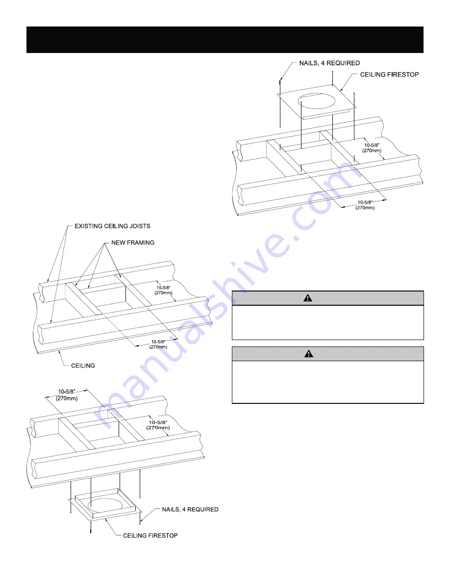
Cut a 10-5/8 inch x 10-5/8 inch hole through the ceiling, using the
center point previously marked. Frame the hole with framing lumber
the same size as the ceiling joists.
See Figure 49.
If the area
above the ceiling is NOT an attic, position and secure the ceiling
¿UHVWRSRQWKHFHLOLQJVLGHRIWKHSUHYLRXVO\FXWDQGIUDPHGKROH
See Figure 50.
If the area above the ceiling is an attic, position
DQGVHFXUHWKH¿UHVWRSRQWRSRIWKHSUHYLRXVO\IUDPHGKROH
See
Figure 51.
NOTE:
Remove insulation from the framed area in the attic before
LQVWDOOLQJWKH¿UHVWRSDQGRUYHQWSLSHV
Figure 49
Figure 50
Figure 51
Finishing
Finish the walls with the material of your choice.
Figure 2
on Page 9
shows the minimum vertical and corresponding maximum horizontal
dimensions of mantels or other combustible projections above the
WRSIURQWHGJHRIWKH¿UHSODFH
Only non-combustible materials may be used to cover the black
¿UHSODFHIURQW
WARNING
:KHQ ¿QLVKLQJ WKH ¿UHSODFH QHYHU REVWUXFW RU PRGLI\ WKH
air inlet/outlet louvers in any manner. Provide adequate
clearances around air openings into the combustion
chamber.
CAUTION
,IWKHMRLQWVEHWZHHQWKH¿QLVKHGZDOODQGWKH¿UHSODFHVXUURXQGWRS
and sides) are sealed, a 300 Degree F minimum sealant material
must be used. These joints are not required to be sealed. Only
non-combustible material (using 300 Degree F minimum adhesive
LIQHHGHGFDQEHDSSOLHGDVIDFLQJWRWKH¿UHSODFHVXUURXQG


