background image

27

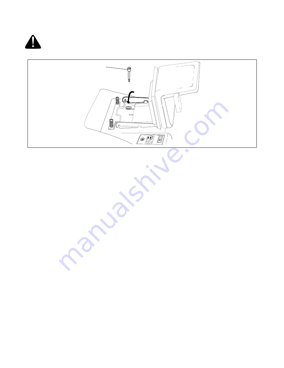
ADDING HYDRAULIC OIL

WARNING: 

Never overfill the hydraulic units. Damage can result if the oil level is not within the

operating range.

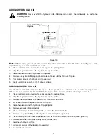
Figure 16  

Note: 

When adding hydraulic oil, do so in small quantities and recheck the oil level before adding more.  It is

important that you do not over fill the reservoir.

1.

Place the Z-series on a level surface and engage the parking brake.

2.

Stop the engine and remove the key from the ignition switch.

3.

Clean the area around the Hydraulic Oil Dipstick.

4.

Remove the hydraulic fill plug and insert a clean funnel into the hydraulic fill point.

5.

Pour proper amount of hydraulic oil into reservoir.

6.

Insert the dipstick and check the hydraulic oil level.

DRAINING HYDRAULIC OIL

Used hydraulic oil must be disposed of properly.  Do not pour it down a drain or sewer, or dump it on open land,
this creates an environmental hazard.  Please be aware of the environment when disposing of used oil.

1.

Place the Z-series on a level surface and engage the parking brake.

2.

Stop the engine and remove the key from the ignition switch.

3.

Remove the mower deck. See  REMOVING THE MOWER DECK. 

4.

Move seat forward to expose hydraulic oil fill point.

5.

Clean the area around the hydraulic fill plug/dipstick.

6.

Remove hydraulic fill plug/dipstick.

7.

Place a suitable (at least 2 gallon) container under the hydraulic oil filter.

8.

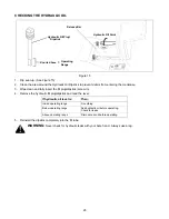
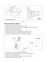
Remove the hydraulic filter to allow hydraulic oil to drain. (See Figure 17)

9.

Place a small pan under the skid plate and drain oil from both left and right axles. (See Figure 17)

10. Replace both axle drain plugs and hydraulic oil tank plug.

11. Install new hydraulic oil filter.

12. Add proper amount of hydraulic oil to reservoir.

13. Run and check oil level.

Hydraulic Fill Point

Hydraulic Fill Plug/
Dipstick

Summary of Contents for 180, 180L, 200

Page 1: ...eting applicable local or state laws if any If a spark arrester is used it should be maintained in effective working order by the operator In the State of California the above is required by law Section 4442 of the California Public Resources Code Other states may have similar laws Federal laws apply on federal lands A spark arrester for the muffler is available through your nearest engine authori...

Page 2: ... battery stand It is located on the rear face of the battery stand Figure 1 SECTION 2 CALLING WARRANTY SERVICE If you are having difficulty assembling this product or if you have any question regarding the controls operation or maintenance of this unit please call the Customer Dealer Referral Line You can reach them by calling 1 800 949 4483 Before calling your local dealer make sure that you have...

Page 3: ...se and backing up Always look down and behind before and while backing Be aware of the mower and attachment discharge direction and do not point it at anyone Do not operate the mower without either the entire grass catcher or the chute guard in place Slow down before turning Operate the machine smoothly Avoid erratic operation and excessive speed Never leave a running machine unattended Always tur...

Page 4: ...the machine and the mowing activity Never assume that chil dren will remain where you last saw them Keep children out of the mowing area and in watchful care of an adult other than the operator Be alert and turn machine off if children enter the area Before and when backing look behind and down for small children Never carry children They may fall off and be seriously injured or interfere with the...

Page 5: ...proper disposal laws and regulations Improper disposal of fluids and materials can harm the environment and the ecology Prior to disposal determine the proper method to dispose of waste from your local Environmental Protection Agency Recycling centers are established to properly dispose of materials in an environmentally safe fashion Use proper containers when draining fluids Do not use food or be...

Page 6: ...o not mow on inclines with a slope in excess of 15 degrees a rise of approximately 2 1 2 feet every 10 feet A riding mower could overturn and cause serious injury If operating a walk behind mower on such a slope it is extremely difficult to maintain your footing and you could slip resulting in serious injury Operate RIDING mowers up and down slopes never across the face of slopes Operate WALK BEHI...

Page 7: ...e to determine when maintenance is required and to cost jobs RPM METER When the engine is on the meter functions as an engine RPM gauge POWER TAKE OFF PTO SWITCH Figure 4 The PTO switch is located on the Right Control Panel See Figure 4 It controls the engagement of the cutting blades When the switch is UP The cutting blades are engaged blades are turning DOWN The cutting blades are disengaged not...

Page 8: ... used by the Z series See Figure 3 See Figure 6 1 through 7 1 lowest height 7 highest height L is the lock out position The lock position is used when removing the mower deck The Choke Lever is located on the Left Control Panel See Figure 7 The Choke Lever is operated manually Having the Choke Lever in the ON position helps the engine to start during initial start up During normal operation the Ch...

Page 9: ...the Control Tower See Figure 8 The drive handles are used to move propel steer and stop the Z series The drive handles will return toward the neutral position without driver input However the driver should place the Drive Handles in the neutral position Unless the Drive Handles are placed in the neutral position the Z Series may creep When the Drive Handles are in the neutral position the unit doe...

Page 10: ... combination i e Left push Right pull NOTE The Drive Handles will return toward neutral when released but they should be placed in neutral by the driver If the Drive Handles are not placed in neutral the tractor may creep Figure 9 SPEED CONTROL BAR The Speed Control Bar is connected to the console with two wing nuts See Figure 9 It is used as a grab bar for entry or exit from the tractor and allow...

Page 11: ...ery Stop the Z series and contact your dealer TEMPERATURE Liquid Cooled Models only Stop the engine immediately Check clean air intake and cooling areas SEAT ADJUSTMENT LEVER Figure 11 The Seat Adjustment Lever is located beneath the seat See Figure 11 The Seat Adjustment Lever is used to move the seat forward and backward 1 Pull up on the seat adjustment lever and push the seat forward or back to...

Page 12: ...e engine is hot STARTING THE ENGINE The Z series is equipped with a safety interlock system with the following features The engine will not crank or start without the Parking Brake fully engaged and the PTO disengaged down If the operator dismounts the tractor with the PTO in the RUN position or the Parking Brake disengaged it automatically shuts the engine off WARNING During operation do not run ...

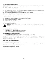
Page 13: ...n 4 Allow the engine to idle for a few seconds 5 Turn the key to the OFF position WARNING Always remove the key from the ignition switch to avoid accidental starting and battery discharge OPERATING THE CHOKE LEVER ON Push the lever forward toward the front of the tractor OFF Pull the lever back toward the rear of the tractor OPERATING THE THROTTLE LEVER FASTER ENGINE SPEED Push the throttle lever ...

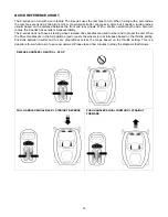
Page 14: ...s excellent maneuverability The Z series does not have a steering wheel instead drive handles are used to steer and to propel the unit When the Drive Handles are in the full positions pull or push the wheels turn at full speed based on the throttle setting Positions between neutral and full are proportional across the range based on the throttle setting This is a departure from what most of us are...

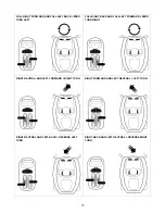
Page 15: ...ERO TURN LEFT FULL RIGHT BACK AND FULL LEFT FORWARD ZERO TURN RIGHT RIGHT NEUTRAL AND LEFT FORWARD RIGHT TURN RIGHT FORWARD AND LEFT NEUTRAL LEFT TURN RIGHT NEUTRAL AND LEFT BACK REVERSE LEFT TURN RIGHT BACK AND LEFT NEUTRAL REVERSE RIGHT TURN ...

Page 16: ...mately 2 1 2 feet every 10 feet Slopes greater can cause the Z series to overturn and cause serious injury Drive UP and DOWN slopes Never drive across slopes Avoid turns If you must turn turn down the slope Turning up a slope greatly increases the chance of roll over Avoid stopping when driving on a slope If you must stop start slowly and smoothly to reduce the chance of flipping the Z series over...

Page 17: ...ntil engine parts have cooled before disengaging 1 Position the Z series on a flat and level surface 2 Engage the parking brake 3 Remove the Hydraulic Relief Levers from the lock position There is a lever for the right and left hydraulic pump 4 Slide the levers into the slots to relieve the hydraulic pumps See Figure 12 5 Disengage parking brake 6 Push unit Right Relief Lever Shown Relief Lever Ne...

Page 18: ... THE BRAKE ADJUSTMENT 1 Position the Z series on a level surface 2 Move the throttle lever to the slowest position turtle 3 Stop the engine and remove the key from the ignition 4 Engage the Parking Brake 5 Release both Hydraulic Relief Levers 6 From the rear push on the frame and try to move the Z series 7 Release the Parking Brake Try again to move the Z series by pushing If you Then Can move it ...

Page 19: ...gure 13 4 The factory sets a 1 16 gap minimum between the brake arm and frame of the Z Series More adjustment may be necessary See Figure 13 NOTE If after adjusting the brake the proper force has not been obtained more adjustment may be required 5 Repeat process on the other brake rod 6 Check the operation of the brakes before operating If the adjustment does not help see your dealer If Then Incre...

Page 20: ...o upper control handles and lower control arms The shock absorbers should remain connected to linkage 10 Insert quarter inch by seven inch pin or equivalent through the top and bottom alignment holes B of the control arms to secure arms at positive neutral Remove floor for access to lower holes 11 With the shock absorber still bolted to linkage loosen the jam nuts C at both ends of the linkage so ...

Page 21: ... holes 17 Set parking brake and start the engine set throttle at full speed Make sure that the PTO is off 18 Rotate rods lengthen or shorten to bring each hydrostat to neutral Note The control linkage going to the hydrostatic pump has left hand threads at the pump and right hand threads at the tower 19 Tighten the jam nuts earlier loosened 20 Reassemble safety switches 21 Reassemble body panels 22...

Page 22: ...es minimum of lubricator using 251 H EP grease or equivalent No 2 multi purpose lithium grease refer to GREASE POINT LOCATIONS on page 23 for locations Lift Arms 50 Hours Two strokes minimum of lubricator using 251 H EP grease or equivalent No 2 multi purpose lithium grease refer to GREASE POINT LOCATIONS on page 23 for locations Lift Handle 50 Hours Two strokes minimum of lubricator using 251 H E...

Page 23: ...ttings Caster Wheel Spindle Grease Fitting Found on both left and right caster spindles Steering Linkage Grease Fittings Caster Wheel Grease Fitting Found on both left and right caster hubs Pivot Bar Grease Fitting Found centered below steering column Deck Lift Pivot NOTE Grease fitting not shown Located under engine on idler arm ...

Page 24: ...e the seat completely forward 2 Move the deck lift lever to position 3 3 Tilt the seat forward 4 Lift the bar under the rear of the seat and slide the entire seat assembly forward 5 Grasp and lift the body panel 6 Use the prop rod to hold the panel open Place prop rod on left hand side of latch Bar Seat Latch Prop Rod ...

Page 25: ...LIC OIL LEVEL Check the oil level of hydraulic units only when the Engine is off not running Practice the following maintenance schedule when checking hydraulic oil Note Close monitoring of the hydraulic oil is always important but is especially critical during the first 5 hours of operation If Check oil Initial break in first 5 hours of operation Before each use and after every hour of operation ...

Page 26: ...ill plug dipstick and read the level 5 Reinstall the dipstick completely into the fill tube WARNING Never check for hydraulic leaks with your bare hand Always use a rag If hydraulic oil level is Then Inside operating range Do nothing Below operating range Add hydraulic oil before operating Check for leaks Above operating range Drain excess oil before operating Hydraulic Fill Plug Dipstick Operatin...

Page 27: ...pour it down a drain or sewer or dump it on open land this creates an environmental hazard Please be aware of the environment when disposing of used oil 1 Place the Z series on a level surface and engage the parking brake 2 Stop the engine and remove the key from the ignition switch 3 Remove the mower deck See REMOVING THE MOWER DECK 4 Move seat forward to expose hydraulic oil fill point 5 Clean t...

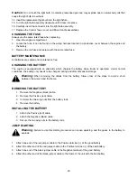
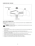
Page 28: ...ol Tower cover 7 Pull up on the Control Tower cover and slide up and over the Control Tower 8 Locate the rear of the light fixture where the wire attaches See Figure 18 Figure 18 9 Remove the wire from the light bulb assembly See Figure 18 10 Squeeze the tab on the connector that attaches the wire to the light bulb assembly 11 Pull the wire from the light bulb assembly 12 Turn the light bulb assem...

Page 29: ...tery when tractor is operated Under normal conditions the battery only needs to be charged during and after off season storage Warning When removing the cables from the battery follow order of the steps to avoid a short between the wrench and the frame REMOVING THE BATTERY 1 Remove the Negative black cable 2 Remove the Positive red cable 3 Unscrew the two wing nuts from the battery rods 4 Remove t...

Page 30: ...tery from unit is recommended TIRES The two front wheels are caster wheels that are free to swivel to accommodate the direction of the Z series The tires on the caster wheels are made of solid polyurethane that do not require air The two rear wheels are used to propel the Z series in the direction of input from the drive handles Inflation pressure of the rear tires is important for stability while...

Page 31: ...e the key 6 Remove spark plug wire s from the spark plug s Access spark plug from the engine compartment 7 Raise the lift handle to the highest setting 7 8 Position the mower blades so that they run perpendicular to the tractor 9 Measure and record the distance from the hard level surface to the outermost edge of the right and left blade See Figure 19 10 Position the mower blades so the ends of ea...

Page 32: ... Back measurements are 0 125 less than the front measurements Lengthen the distance shown on Figure 22 by turning the 90 degree rod one complete turn out Repeat if same result When either side is lower than 4 50 1 Remove the nut and bolt A that holds the hanger link to the hanger bracket on the side that is low See Figure 21 2 Turn the threaded link the appropriate distance up Every 1 2 turn 1 32 ...

Page 33: ...HE MOWER DECK WARNING The cutting blades of the mower deck are sharp and can cause injury 1 Position the Z series on a hard flat surface 2 Engage the Parking Brake 3 Move the lift handle to the L position 4 Remove the wing nuts and then remove the belt covers If Mower Deck is Then 48 or 54 Remove one wing nut for each cover See Figure 23 Hanger Bracket A Hanger Links 11 125 Starting Length ...

Page 34: ...out 10 Move the Lift handle to position 7 all the way up 11 Remove the Belt from the outside pulley of the mower deck by pulling and holding the belt so part of it is outside the pulley 12 Turn the pulley counterclockwise until the belt is completely off of the pulley WARNING Exhaust and surrounding engine parts are very hot and can cause severe burns when touched 13 Locate the Clutch Pulley It is...

Page 35: ...k 18 From the right side pull the mower deck out from under the Tractor 19 To service the blades or the under side of the mower deck there is a mower deck stand that folds out from the top of the mower deck INSTALLING A NEW MOWER DECK BELT 1 Remove the mower deck See REMOVING THE MOWER DECK for details 2 Remove the old belt from the mower deck 3 Install and route the new belt according to the rout...

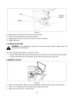
Page 36: ...en the hydraulic units 4 Bring the belt between the pulley and the clutch Do not put the belt into the pulley grove yet 5 From the front of the Z series hold both retaining arms up and slide the mower deck forward until the retaining arms go into the bracket 6 Slide the mower deck backwards to insert the retaining arms into the brackets See Figure 26 7 Align the mower deck so the Lift Lever Bracke...

Page 37: ... a rag to avoid injury Keep the cutting blade sharp and free of build up at all times Sharpen ends of the blades evenly by keeping the same cutting angle to maintain balanced cutting blades Remove debris build up from the underside of the mower deck housing using a putty knife REMOVING A BLADE Figure 28 1 Secure the cutting blade by putting a piece of wood between the blade and the housing See Fig...

Page 38: ... from the engine pulley 7 Now that the belt is slack carefully pull the belt up and over the right hydrostatic cooling fan Now carefully pull the belt up and over the left hydrostatic cooling fan 8 Pull the drive belt out of the unit INSTALLING A NEW DRIVE BELT Follow these instructions to reinstall the drive belt if it has been removed for replacement or if it breaks 1 Set the parking brake 2 Rai...

Page 39: ...hoke to continue operation until all fuel is gone from the carburetor and fuel tank 4 Drain any remaining fuel from the fuel line at the carburetor or gas tank WARNING Drain fuel into an approved container in open air and away from open flames Note Fuel quality deteriorates when fuel is left in engine during warm weather Poor fuel quality can cause engine starting difficulties 5 Crank the engine s...

Page 40: ...s weeds and will yellow quickly in dry conditions During some conditions the mower may leave streaks of uncut material Streaking can happen when cutting heavy weeds and tall grass In these conditions it may be necessary to cut the area a second time for a clean cut AVOIDING STREAKING 1 Mow the area often cutting grass of shorter lengths helps to avoid streaks 2 Operate the Z series at full throttl...

Page 41: ...efill with fresh fuel Clean air cleaner Engine overheats Engine oil level low Air flow restricted Lack of coolant Clogged cooling system Fill crankcase with proper oil Remove blower housing and clean Add coolant to the correct level See your authorized engine service dealer Occasional skip hesitates at high speed Spark plug gap too close Adjust gap to 030 Idles poorly Spark plug fouled faulty or g...

Page 42: ...42 NOTES ...

Page 43: ...43 ...

Page 44: ...or Products Company TRANSPORTATION CHARGES Transportation charges for the movement of any power equipment unit or attachment are the responsibility of the purchaser Transportation charges for any parts submitted for replacement under this warranty must be paid by the purchaser unless such return is requested by White Outdoor Products Company UNITS EXPORTED OUT OF THE UNITED STATES White Outdoor Pr...

Reviews: