background image

12

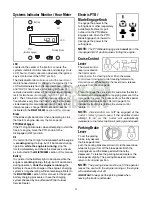
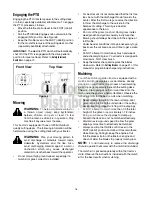
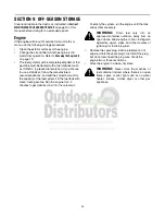
Systems Indicator Monitor / Hour Meter

LCD

Located in the center of the tractor’s console, the 
systems indicator monitor records, and displays on its 
LCD, hours of tractor operation whenever the ignition 
key is rotated out of the STOP position.

The Indicator Monitor will also remind the operator of 
maintenance intervals for changing the engine oil. The 
LCD will alternately flash the recorded hours, “CHG” 
and “OIL” for five minutes, after every 50 hours of 
recorded operation elapse. The maintenance interval 
lasts for two hours (from 50-52, 100-102, 150-152, 
etc.). The LCD will also flash as described above for 
five minutes every time the tractor’s engine has been 
started during this maintenance interval. Before the 
interval expires, change the crankcase oil level as 
instructed in the 

MAINTENANCE

 section of this manual.

Brake 

If the Brake light illuminates when attempting to start 
the tractor’s engine, depress the brake pedal.

PTO (Blade Engage)

If the PTO light illuminates when attempting to start the 
tractor’s engine, move the PTO knob into the 
disengaged (OFF) position.

Oil

It is normal for the Oil light to illuminate while the engine 
is 

cranking

 during start-up, but if it illuminate’s during 

operation, 

while the engine is running

, stop the 

tractor immediately and check the crankcase oil level 
as instructed in the 

MAINTENANCE

 section of this manual.

Battery

It is normal for the Battery light to illuminate while the 
engine is 

cranking

 during start-up, but if it illuminate’s 

during operation, 

while the engine is running

, the 

battery is in need of a charge or the engine’s charging 
system is not generating sufficient amperage. Refer to 
the 

MAINTENANCE

 section of this manual for the proper 

battery charging procedure or have the charging 
system checked by an authorized 

White Outdoor


Service Dealer.

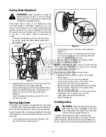
Electric PTO /
Blade Engage Knob

To engage the power to the 
cutting deck or other (separately 
available) attachments, pull 
outward on the PTO/Blade 
Engage knob. Push the PTO/
Blade Engage knob inward to 
disengage the power to the 
cutting deck.

NOTE: 

The PTO/Blade Engage knob 

must

 be in the

disengaged (OFF) position when starting the engine.

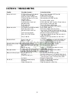
Cruise Control 
Lever 

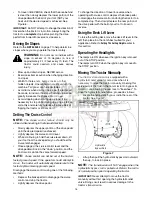
The cruise control 
lever is located on 
the tractor dash 
panel, below the steering wheel. Push the cruise 
control lever downward while traveling forward at a 
desired speed. While holding the lever down, release 
pressure from the drive pedal. 

This will engage the cruise control and allow the tractor 
to remain at that speed without applying pressure to the 
drive pedal. Depress the brake pedal or the drive pedal 
to deactivate cruise control. Refer to page 15 for 
detailed instructions regarding the cruise control 
feature.

NOTE: 

Cruise control can NOT be engaged at the

tractor’s fastest ground speed. If the operator should
attempt to do so, the tractor will automatically
decelerate to the fastest optimal mowing ground speed.

Parking Brake 
Lever 

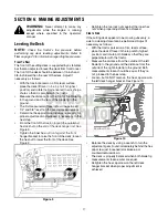
To set the parking 
brake, fully depress 
the brake pedal and 
push the parking brake lever down. Hold the lever down 
while taking your foot off the brake pedal. Both the 
parking lever and the brake pedal will then stay 
depressed. To release the parking brake, depress the 
brake pedal slightly. The parking brake lever will then 
return to its original position.

NOTE: 

The parking brake must be set if the operator

leaves the seat with the engine running or the engine
will automatically shut off.

IMPORTANT:

 Always set the parking brake when 

leaving the tractor unattended.

Battery

LCD

PTO

(Blade Engage)

Oil

Parking Brake

42.0

Summary of Contents for GT 954H

Page 1: ...state laws if any If a spark arrester is used it should be maintained in effective working order by the operator In the State of California the above is required by law Section 4442 of the California Public Resources Code Other states may have similar laws Federal laws apply on federal lands A spark arrester for the muffler is available through your White Outdoor dealer or contact the service depa...

Page 2: ...ntrols operation or maintenance of this unit you can seek help from the experts To reach a local White Outdoor dealer or retailer visit www whiteoutdoor com or phone our Dealer Locator line at 800 949 4483 ENGINE INFORMATION The engine manufacturer is responsible for all engine related issues with regard to performance power rating specifications warranty and service Please refer to the engine man...

Page 3: ...ersonal injury 7 Plan your mowing pattern to avoid discharge of material toward roads sidewalks bystanders and the like Also avoid discharging material against a wall or obstruction which may cause discharged material to ricochet back toward the operator 8 Always wear safety glasses or safety goggles during operation and while performing an adjustment or repair to protect your eyes Thrown objects ...

Page 4: ...r shift while on the slope Tires may lose traction on slopes even though the brakes are functioning properly Always keep machine in gear when going down slopes to take advantage of engine braking action 4 Follow the manufacturer s recommendations for wheel weights or counterweights to improve stability 5 Use extra care with grass catchers or other attachments These can change the stability of the ...

Page 5: ...ling is complete Do not use a nozzle lock open device e Extinguish all cigarettes cigars pipes and other sources of ignition f Never fuel machine indoors g Never remove gas cap or add fuel while the engine is hot or running Allow engine to cool at least two minutes before refueling h Never over fill fuel tank Fill tank to no more than inch below bottom of filler neck to allow space for fuel expans...

Page 6: ...mmediately with original equipment manufacturer s O E M parts only listed in this manual Use of parts which do not meet the original equipment specifications may lead to improper performance and compromise safety 12 Do not change the engine governor settings or over speed the engine The governor controls the maximum safe operating speed of the engine 13 Maintain or replace safety and instruction l...

Page 7: ...P E Do not mow on inclines with a slope in excess of 15 degrees a rise of approximately 2 1 2 feet every 10 feet A riding mower could overturn and cause serious injury If operating a walk behind mower on such a slope it is extremely difficult to maintain your footing and you could slip resulting in serious injury Operate RIDING mowers up and down slopes never across the face of slopes WARNING ...

Page 8: ...WARNING Make sure the engine is off set the parking brake and remove the ignition key before removing the shipping brace Locate the shipping brace if present and warning tag found on the right side of the cutting deck While holding the discharge chute with your left hand remove the shipping brace with your right hand by grasping it between your thumb and index finger and rotating it clockwise WARN...

Page 9: ...etween the bottom of the wheel and the pavement e Note the position of the index hole used then install the other gauge wheel into the corresponding index hole of the other gauge wheel brackets If the gauge wheels have excessive clearance with the surface below lower the wheels to the index hole that provides the approximate 1 2 clearance as described above Figure 2 Roller To adjust the height of ...

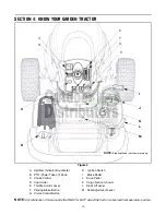
Page 10: ...osition A Systems Indicator Hour Meter H Ignition Switch B PTO Power Take off Knob I Brake Pedal C Choke Control J Drive Pedal D Cup Holder K Cargo Net not shown E Throttle Control Lever L Deck Lift Lever F Parking Brake Button M Seat Adjustment Lever G Cruise Control Button H E A C G F D L J I M NOTE Steering Wheel not shown for clarity P 1 10 P B K ...

Page 11: ...e deck lift lever is used to change the height of the cutting deck To use move the lever to the left then place in the notch best suited for your application Ignition Switch Module WARNING Never leave a running machine unattended Always disengage PTO move shift lever into neutral position set parking brake stop engine and remove key to prevent unintended starting To start the engine insert the key...

Page 12: ...tion of this manual for the proper battery charging procedure or have the charging system checked by an authorized White Outdoor Service Dealer Electric PTO Blade Engage Knob To engage the power to the cutting deck or other separately available attachments pull outward on the PTO Blade Engage knob Push the PTO Blade Engage knob inward to disengage the power to the cutting deck NOTE The PTO Blade E...

Page 13: ...VERSE CAUTION MODE IMPORTANT The operator MUST be seated in the tractor seat 1 Start the engine as previously instructed in this Operator s Manual 2 Turn the key from the NORMAL MOWING Green position to the REVERSE CAUTION MODE Yellow position of the key switch module See Figure 5 3 Depress the REVERSE PUSH BUTTON Orange Triangular Button at the top right corner of the key switch module The red in...

Page 14: ...ce the PTO Blade Engage knob in the disengaged OFF position Place the throttle control near the FAST position Turn the ignition key counterclockwise to the STOP position Remove the key from the ignition switch to prevent unintended starting Engaging the Parking Brake To engage the parking brake Fully depress the brake pedal and hold it there while gently pushing the parking brake lever downward Ho...

Page 15: ...ctor will maintain the same forward speed NOTE Cruise control can not be set at the tractor s fastest ground speed If the operator should attempt to do so the tractor will automatically decelerate to the fastest optimal mowing ground speed Disengage the cruise control using one of the following methods Depress the brake pedal to disengage the cruise control and stop the tractor Lightly depress the...

Page 16: ...vites weed growth and yellows quickly in dry weather Mowing should always be done with the engine at full throttle Under heavier conditions it may be necessary to go back over the cut area a second time to get a clean cut Do NOT attempt to mow heavy brush and weeds and extremely tall grass Your tractor is designed to mow lawns NOT clear brush Keep the blades sharp and replace the blades when worn ...

Page 17: ...outermost hex lock nut on the end of the deck hanger rod See Figure 9 Tighten the inner hex nut front against the front hanger bracket to raise the front of the deck loosen the hex nut to lower the front of the deck See Figure 9 Figure 9 Retighten the two lock nuts against the inner hex nuts when proper adjustment is achieved Side to Side If the cutting deck appears to be mowing unevenly a side to...

Page 18: ...igure 12 Figure 12 Remove the hex nut on the top of ball joint See Figure 12 Thread the ball joint toward the jam nut to shorten the drag link Thread the ball joint away from the jam nut to lengthen the drag link Replace hex nut and retighten the jam nut after proper adjustment is achieved NOTE Threading the ball joints too far onto the drag links will cause the front tires to toe in too far Prope...

Page 19: ...ark plugs and reset the gap once a season Spark plug replacement is recommended at the start of each mowing season Refer to the engine manual for correct plug type and gap specifications Cleaning the Engine and Deck Promptly wipe off any fuel or oil spilled on the machine Do not allow grass leaves and dirt to accumulate around the cooling fins of the engine or on any other part of the machine espe...

Page 20: ...ply two strokes minimum or sufficient grease to each spindle Rear Wheels The rear wheels should be removed from the axles once a season Lubricate the axles and the rims well with an all purpose grease before re installing them Front Wheels Each of the front wheel axles is equipped with a grease fitting Lubricate with 251H EP grease or an equivalent No 2 multi purpose lithium grease after every 25 ...

Page 21: ...al separation is present replace the blades with new ones See Figure 16 It is important that each cutting blade edge be ground equally to maintain proper blade balance A poorly balanced blade will cause excessive vibration and may cause damage to the tractor and result in personal injury IMPORTANT When replacing the blade be sure to install the blade with the side of the blade marked Bottom or wit...

Page 22: ...he bottom notch on the right fender Remove the deck belt from around the tractor s electric PTO clutch refer to Changing the Deck Belt Looking at the cutting deck from the left side of the tractor locate the deck support pin on the rear left side of the deck Rotate the pin slightly toward the rear of the tractor and release the pin into the hole provided Pull the deck support pin outward to releas...

Page 23: ...r pulley s may have to be loosened but not removed in order to remove the belt from around them Route the new belt as shown in Figure 19 below Remount the belt guards removed earlier Changing The Transmission Drive Belt NOTE Several components must be removed and special tools i e air impact wrench used in order to change the tractor s transmission drive belt See your White Outdoor dealer to have ...

Page 24: ...ecommendations and add the correct amount for the capacity of the fuel system Fill the fuel tank with clean fresh gasoline Run the engine for 2 3 minutes to get stabilized fuel into the carburetor To empty the system run the engine until the tank and system are empty WARNING Drain fuel only into an approved container outdoors away from an open flame Allow engine to cool Extinguish cigarettes cigar...

Page 25: ...replace cap if damaged Drain fuel tank Refill with clean fresh less than 30 days old gasoline Replace air cleaner paper element or clean foam precleaner Engine overheats Engine oil level low Air flow restricted Fill crankcase with proper capacity and weight of oil Clean grass clippings and debris from around the engine s cooling fins and blower housing Engine hesitates at high RPM Spark plug gap t...

Page 26: ...Sleeve Hitch with Electric Lift OEM 190 842 Triple Bagger Grass Collector OEM 190 784 Rear Wheel Weights OEM 190 604 Tool and Storage Chest OEM 190 672 Bumper Kit OEM 190 607 Deluxe Tractor Sunshade OEM 190 750 Tractor Snow Cab OEM 190 184 40 Dethatcher Not compatible with tractors equipped with a Grass Collector SLEEVE HITCH ATTACHMENTS OEM 190 825 30 inch Hydraulic Tiller OEM 190 978 10 inch Mul...

Page 27: ...27 NOTES ...

Page 28: ...8 A B B A 20 3 8 5 21 1 13 17 10 20 7 3 14 12 17 35 5 34 32 28 27 29 4 25 23 38 39 42 24 33 36 22 26 31 43 30 45 44 17 9 3 19 22 11 2 41 18 40 3 17 4 6 15 5 16 37 SECTION 12 PARTS LIST FOR MODEL GT 954H ...

Page 29: ...017 Screw 1 4 14 0 625 24 710 1611B Screw 5 16 18 0 750 25 710 3217 Screw Machine 8 32 0 375 26 712 0142 Nut Hex 8 32 27 731 04213 Brake Lever 28 731 04214 Cruise Control Lever 29 731 05037 Dash Panel 30 731 1857 Control Knob 31 746 1085A Choke Knob w Cable 37 5 32 747 1155 Rod Brake Cruise Pivot 33 783 04285D Support Plate Dash RH 34 783 04323D Support Plate Dash LH 35 725 1752 Electric PTO Switc...

Page 30: ...30 Model GT 954H 39 46 14 40 45 37 43 14 36 48 50 14 8 10 20 12 23 21 22 24 6 2 52 18 25 19 5 3 6 26 32 49 47 44 16 30 28 38 33 27 31 34 51 11 28 13 35 54 58 59 56 57 9 55 42 21 15 7 41 53 1 6 4 17 29 ...

Page 31: ...0 0604A Self tapping Screw 5 16 18 x 625 29 710 0895 Self tapping Screw 1 4 15 x 75 30 731 1990 Lift Lever Cover 31 731 1993A Cover w Cup Holder 32 736 3078 Flat Washer 349 x 1 0 x 063 33 783 0677B Lift Adjustment Bracket 34 783 04459A Fender 4 Sty Hydro w Flares 35 783 1489B Seat Mounting Bracket 36 710 1268 Screw 10 16 x 375 37 712 04064 Flange Lock Nut 1 4 20 38 720 0309A Seat Adjuster Grip 39 ...

Page 32: ...32 25 3 14 24 15 12 8 19 9 6 26 17 1 17 39 29 13 10 33 37 28 29 31 30 5 11 28 32 2 39 18 20 27 4 22 21 16 7 16 38 7 23 36 35 34 Model GT 954H ...

Page 33: ... 738 1001A Shaft Steering 625 OD x 24 25 Lg 19 741 0475 Plastic Bushing 380 ID 20 741 0656A Hex Flange Bearing 5 8 PM 21 783 0726E Pivot Bracket Support RH 22 783 0727D Pivot Bracket Support LH 23 783 0728 Pivot Bracket Bar 24 631 04008A Steering Wheel 13 25 25 731 04065 Steering Wheel Cover 26 738 1011A Shoulder Screw 5 x 2 2 3 8 16 27 734 2290A Deluxe Hub Cap 28 736 0316 Flat Washer 78 x 1 589 x...

Page 34: ... 26 15 15 16 16 64 62 61 17 54 59 46 16 41 60 51 67 27 9 16 48 16 66 13 47 57 63 54 59 60 17 49 71 44 50 42 4 68 17 38 5 1 14 8 2 24 16 31 22 27 73 75 65 76 20 For Ground Wire Reverse Adapter Assembly 78 39 77 81 79 73 18 To Attach Reverse Assembly Adapter To Main Harness 56 17 40 72 73 ...

Page 35: ...7 0031B Brake Control Assembly 41 647 0049A Drive Control Assembly 42 683 0267C Hydro Pedal Assembly 43 710 0650 Self tapping Screw 5 16 18 x 875 44 710 1260A Self tapping Screw 5 16 18 x 75 46 711 04159B Pin 3 8 16 x 2 43 47 732 0335 Compression Spring 40 OD x 1 17 48 732 0955 Extension Spring 50 OD x 1 41 49 732 0963 Extension Spring 50 OD x 6 37 50 735 0662 Drive Pedal Pad 51 735 3049 Brake Ped...

Page 36: ...36 1 27 26 32 34 33 14 12 22 24 24 28 29 25 20 23 18 21 16 19 17 4 23 31 30 20 4 24 11 13 15 10 8 6 7 3 2 35 9 5 36 Model GT 954H ...

Page 37: ...Screw 10 16 x 500 16 683 04173 Frame Assembly Lower 17 710 0607 Screw 5 16 18 0 500 18 710 0642 Screw 1 4 20 0 750 19 710 3005 Screw 3 8 16 1 25 Gr5 20 712 04064 Nut Flange Lock 1 4 20 GrF Nylon 21 783 0693 Axle Bracket 22 732 04035 Spring Compression 1 28 OD x 3 125 23 736 0222 Washer Lock 1 4 External 24 710 0726 Screw 5 16 12 0 75 25 738 04058 Spacer Shoulder 38 x 1 0 x 70 26 747 04121A Hold Ro...

Page 38: ...5 11 57 68 56 73 29 69 5 68 60 57 20 36 46 63 4 15 51 40 6 17 75 3 67 3 7 14 16 21 47 58 32 30 54 31 24 71 1 35 39 59 38 65 43 65 39 18 27 38 10 18 27 29 A A 55 33 62 28 22 70 77 52 29 9 41 17 78 42 19 34 76 13 17 48 53 17 783 0720A Shown for Ref Only 683 04118 Shown for Ref Only ...

Page 39: ...712 3022 Nut Hex Lock 1 2 13 34 712 3083 Hex Lock Nut 1 2 13 35 714 0145 Pin Click 092 x 1 64 36 714 0470 Pin Cotter 1 8 x 1 25 37 714 0111 Pin Cotter 3 32 x 1 00 38 715 0108 Pin Spring 1 4 Dia x 1 00 39 714 0162 Cotter Pin 40 717 04074 Adjustment Deck Gear 41 721 04041 Water Nozzle Adaptor 42 747 1324 Rod Deck Adjust 43 731 0335 Roller Deck 44 731 3005 Front Roller 45 731 05559 Deflector Chute 46...

Page 40: ... 751 3142 Oil Drain Cap 6 710 0654A Self tapping Screw 3 8 16 x 1 00 7 712 3005 Flange Lock Nut 3 8 16 8 751 3141 Oil Drain Hose 9 726 0205 Hose Clamp 10 725 0157 Cable Tie 11 736 0300 Lock Washer 406 x 875 x 059 12 751 3140 Oil Drain Valve 13 751 10349 Fuel Line Hose 14 751 0564A Muffler Deflector 15 751 0805A Muffler Twin Inlet 16 751 0645A RH Exhaust Pipe 17 751 0644 LH Exhaust Pipe REF NO PART...

Page 41: ... 3NOWTHROWER 3LEEVE ITCH WITH LECTRIC IFT 3LEEVE ITCH ANUAL IFT 4OOL AND 3TORAGE HEST 2OW ROP ULTIVATOR 3INGLE ISC ARROW OLDBOARD 0LOW EAVY UTY 2EAR LADE 4ILLER NLY VAILABLE 7ITH LECTRIC 3LEEVE 4 6 3 2 53 529 2 4 s 50 7 3 0 3 4 2 33 s 6 35 452 3 s 4 0 2 4 4 5 4 7 2 4 5 3 0 2 4 0 s 34 03 50 34 0 3 7 3 7 9 s 0 3 49 6 3 5 2 3 3 3 37 4 3 4 0 7 2 s 2 6 43 4 4 5 4 2 7 9 4 3 s 7 4 5 4 42 3 s 352 3 2 34 0...

Page 42: ...42 NOTES ...
Page 43: ...warranty period stated above If the part fails during the period of warranty coverage the part will be repaired or replaced by MTD Consumer Group Inc according to subsection 4 below Any such part repaired or replaced under warranty will be warranted for the remainder of the period 2 Any warranted part that is scheduled only for regular inspection in the written instructions supplied is warranted f...

Page 44: ...djustments and normal deteriora tion of the exterior finish due to use or exposure d Service completed by someone other than an autho rized service dealer e MTD does not extend any warranty for products sold or exported outside of the United States its posses sions and territories except those sold through MTD s authorized channels of export distribution f Replacement parts that are not genuine MT...

Reviews: