background image

Page

181-887-14

9

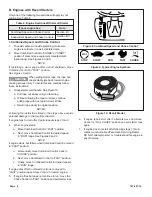
B. Removing Debris from Engine

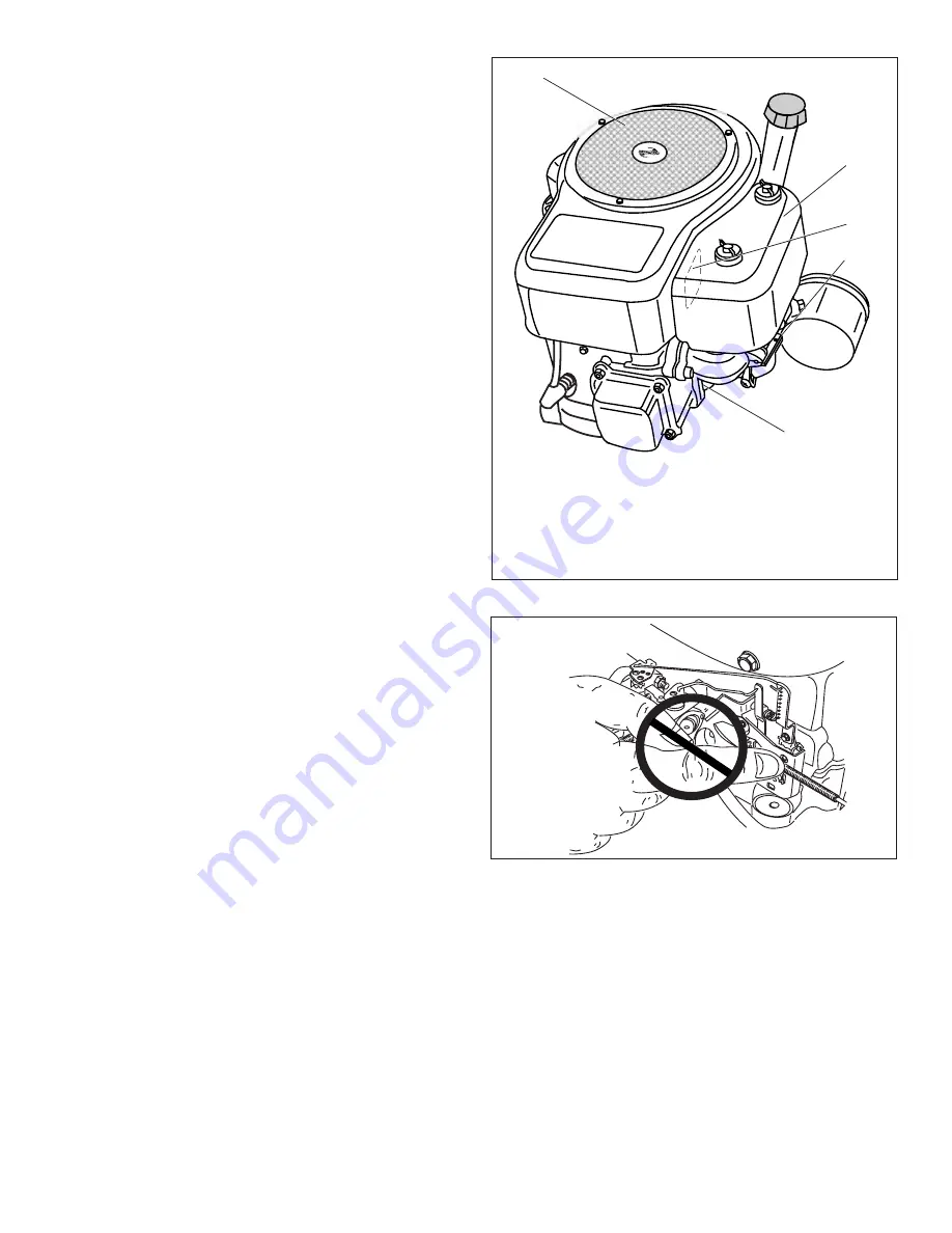
Before each use, remove grass clippings, dirt and debris
from the following areas:

•  Cooling fins
• Air intake screen
•  Levers
•  Linkage
•  Air Inlet

NOTES

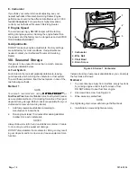
See “III. Filter Removal/Installation” instructions before re-
moving Air Cleaner Cover. Special care should be taken to
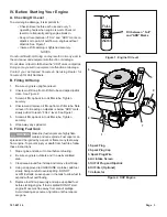
prevent damage when removing air cleaner  cover. See Figure
16.

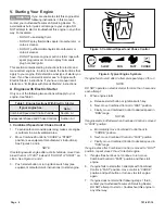
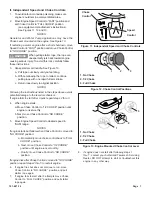
DO NOT bend levers and linkage with fingers. See Figure 17.

1.

See “III. Filter Removal/Installation” instructions.

2.

Remove Air Cleaner Cover and filters. See Figure 16.

3.

Remove debris from air inlet, air cleaner cover and air
intake screen.

4.

Inspect filter(s) for discoloration or dirt accumulation. If
either is present, see “Servicing Filters” instructions.

5.

Replace Air Cleaner Cover and Filters.

Removing debris will insure adequate cooling, correct engine
speed and reduce the risk of fire.

Figure 17. Linkage and Lever Bending

1. Cooling Fins
2. Levers and Linkage
3. Air Inlet
4. Air Cleaner Cover
5. Air Intake Screen

5

3
2

1

4

Figure 16. Debris Locations

Summary of Contents for LT 165

Page 1: ...d with a spark arrester meeting applicable local or state laws if any If a spark arrester is used it should be maintained in effective working order by the operator In the State of California the above is required by law Section 4442 of the California Public Resources Code Other states may have similar laws Federal laws apply on federal lands A spark arrester for the muffler is available through y...

Page 2: ... very important if you need help from your White Outdoor dealer You can locate the model number by looking beneath the seat A sample model plate is explained below For future reference please copy the model number and the serial number of the equipment in the space below CALLING CUSTOMER SUPPORT If you have difficulty assembling this product or have any questions regarding the controls operation o...

Page 3: ...Plan your mowing pattern to avoid discharge of material toward roads sidewalks bystanders and the like Also avoid discharging material against a wall or obstruction which may cause discharged material to ricochet back toward the operator 8 Always wear safety glasses or safety goggles during operation and while performing an adjustment or repair to protect your eyes Thrown objects which ricochet ca...

Page 4: ...ss can hide obstacles 3 Use slow speed Choose a low enough speed setting so that you will not have to stop or shift while on the slope Tires may lose traction on slopes even though the brakes are functioning properly Always keep machine in gear when going down slopes to take advantage of engine braking action 4 Follow the manufacturer s recommendations for wheel weights or counterweights to improv...

Page 5: ... gas powered equipment from the truck or trailer and refuel it on the ground If this is not possible then refuel such equipment on a trailer with a portable container rather than from a gasoline dispenser nozzle d Keep the nozzle in contact with the rim of the fuel tank or container opening at all times until fueling is complete Do not use a nozzle lock open device e Extinguish all cigarettes ciga...

Page 6: ...tc to protect the environment WARNING YOUR RESPONSIBILITY Restrict the use of this power machine to persons who read understand and follow the warnings and instructions in this manual and on the machine WARNING GO UP AND DOWN SLOPES NOT ACROSS AVOID SUDDEN TURNS DO NOT OPERATE THE UNIT WHERE IT COULD SLIP OR TIP IF MACHINE STOPS GOING UPHILL STOP BLADE S AND BACK DOWNHILL SLOWLY DO NOT MOW WHEN CH...

Page 7: ...P E Do not mow on inclines with a slope in excess of 15 degrees a rise of approximately 2 1 2 feet every 10 feet A riding mower could overturn and cause serious injury If operating a walk behind mower on such a slope it is extremely difficult to maintain your footing and you could slip resulting in serious injury Operate RIDING mowers up and down slopes never across the face of slopes WARNING ...

Page 8: ...l prior to operating the tractor Attaching The Steering Wheel The hardware for attaching the steering wheel has been packed within the steering wheel beneath steering wheel cap Carefully pry off the steering wheel cap and remove the hardware Remove the steering bellow from its packaged location on the deck engagement lift lever found on the right hand side of tractor Place the steering bellow over...

Page 9: ... Tire Pressure WARNING Maximum tire pressure under any circumstances is 30 psi Equal tire pressure should be maintained at all times The tires on your unit may be over inflated for shipping purposes Reduce the tire pressure before operating the tractor Recommended operating tire pressure is approximately 10 p s i for the rear tires 14 p s i for the front tires Check sidewall of tire for maximum p ...

Page 10: ...ways in the FAST rabbit position Ignition Switch The ignition switch is located on the right side of the tractor s dash To start the engine insert the key into the ignition switch and turn clockwise to the START position Release the key into the ON position once engine has fired Refer to Starting The Engine on page 12 of this manual for detailed starting instructions A Speed Control Lever E Parkin...

Page 11: ... lever will return to the N Neutral position when the brake pedal is depressed Do NOT attempt to change the direction of travel when the tractor is in motion Always bring the tractor to a complete stop before moving the speed control lever from forward to reverse or vice versa IMPORTANT Always set the parking brake when leaving the tractor unattended Brake Pedal The brake pedal is located on the l...

Page 12: ...fore leaving the operator s position Always place the deck engagement lift lever in the BLADES STOP position place speed control lever in neutral set parking brake stop engine and remove key to prevent unintended starting Move throttle control lever to full throttle NOTE Always operate the tractor with the throttle control lever in the FAST rabbit position for the most efficient use of the cutting...

Page 13: ...r s transmission is equipped with a hydrostatic relief valve for occasions when it is necessary to move the tractor manually Activating this valve forces the fluid in the transmission to bypass its normal route allowing the rear tires to freewheel To engage the hydrostatic relief valve proceed as follows Locate the hydrostatic bypass rod in the rear of the tractor See Figure 6 Pull the hydrostatic...

Page 14: ...ecessary as follows With the tractor parked on a firm level surface place the deck engagement lift lever in the top cutting height notch not BLADES STOP position Rotate the blade nearest the discharge chute so that it is parallel with the tractor Measure the distance from the front of the blade tip to the ground and the rear of the blade tip to the ground The first measurement taken should be betw...

Page 15: ...ver panel in place See Figure 9 Remove the cover panel and locate the deck disengagement rod See Figure 10 Remove the hairpin clip which secures the disengagement rod to the stabilizer shaft assembly See Figure 10 Pull the rod toward the rear of the tractor to take up slack then thread the rod inward or outward usually only one or two turns until the rod lines up as precisely as possible with the ...

Page 16: ...14 0470 is needed to complete this adjustment Have one on hand before proceeding Place the steering wheel in position for straight ahead travel In front of the pivot bar measure the distance horizontally from the inside of the left rim to the inside of the right rim Note the distance Behind the pivot bar measure the distance horizontally from the inside of the left rim to the inside of the right r...

Page 17: ...erator s Manual located after the TROUBLE SHOOTING GUIDE in this manual Perform the above steps in the opposite order after oil has finished draining Refill the engine with approximately 62 oz 1 83 liters of new motor oil IMPORTANT Refer to the White Outdoor Engines Operator s Manual located after the TROUBLE SHOOTING GUIDE in this manual for information regarding the proper weight of motor oil Ai...

Page 18: ...NT If removing the battery for any reason disconnect the NEGATIVE Black wire from it s terminal first followed by the POSITIVE Red wire When re installing the battery always connect the POSITIVE Red wire its terminal first followed by the NEGATIVE Black wire Be certain that the wires are connected to the correct terminals reversing them could change the polarity and cause damage to your engine s a...

Page 19: ...same locations from which they were removed Remove the deck belt from around the engine pulley Return the deck engagement lift lever to the engaged all the way forward position Locate the deck anti sway rod and adjustable deck links found near the front of the cutting deck See Figure 16 Figure 17 First remove the hairpin clip which secures the anti sway rod to the front portion of the cutting deck...

Page 20: ...ee Figure 19 To properly sharpen the cutting blades remove equal amounts of metal from both ends of the blades along the cutting edges parallel to the trailing edge at a 25 to 30 angle See Figure 20 IMPORTANT If the cutting edge of the blade has already been sharpened to within 5 8 of the wind wing radius or if any metal separation is present replace the blades with new ones See Figure 20 It is im...

Page 21: ...e tractor Refer to Cutting Deck Removal on page 19 for detailed instructions Remove the belt guards located over each spindle pulley by removing the self tapping screws which secure them in place See Figure 21 Remove and replace the belt reassemble following the instructions in reverse order Drive Belt NOTE The engine pulley must be removed from the engine s crankshaft in order to change the tract...

Page 22: ...ays prepare for storage as follows Clean the engine and the entire unit thoroughly We do not recommend the use of pressure washers or garden hose to clean your unit They may cause damage to electric components spindles pulleys bearings or the engine The use of water will result in shortened life and reduce serviceability Lubricate all lubrication points Wipe the entire machine with an oiled rag to...

Page 23: ...signed for use with any type of ground engaging attachments e g tiller or plow Use of this type of equipment WILL void the tractor s warranty MODEL DESCRIPTION 190 116 42 inch Deck Mulch Kit 190 180 Twin Bagger Grass Collector 190 215 Rear Wheel Weights Two per set 190 226 Front Bumper Kit 190 620 46 inch Front Dozer Blade 190 627 42 inch Two stage Snow Thrower 190 658 Tire Chains for 20 x 8 0 tir...

Page 24: ...d Note Look for a wire pinched between body panels burned by the exhaust pipe or muffler or rubbed against a moving part Engine should have a black ground wire running from engine to frame or mounting bolt Engine cranks but will not start Throttle or choke not in starting position No fuel to the carburetor No spark to spark plug Dirty air cleaner Check operator s manual for correct position for th...

Page 25: ...25 ...

Page 26: ......

Page 27: ...nsibility to read this Operator s Manual Follow these basic rules for your per sonal safety Keep this manual handy at all times for future reference Read it carefully and familiarize yourself with operating maintenance components and safety instructions Notice Regarding Emissions NOTE Engines which are certified to comply with California and U S EPA emission regulations for SORE Small Off Road Equ...

Page 28: ... Accidental Starts To prevent accidental starting when working on equipment always disconnect spark plug wire and keep it away from spark plug H Stay Away from Rotating Parts Never operate engine with covers or guards removed Rotating parts can cause severe injury Keep hands feet hair jewelry and clothing away from all moving parts A Avoid Carbon Monoxide Poisoning All engine exhaust contains carb...

Page 29: ...Decal includes engine life specifications for the emissions related useful life period of your engine This period relates to the emission compliance life as certified by EPA CARB To find the life period specification for your engine please look on your decal and find the letter en closed by quotation marks in between the words MODER ATE and LIFE PERIOD Match one of the following letters with the l...

Page 30: ...w oil fill cap from oil filler tube and wipe dipstick clean See Figure 2 3 Screw oil fill cap back into oil filler tube Tighten securely 4 Unscrew and remove oil fill cap from oil filler tube Note oil level If oil reading on dipstick is below ADD mark slowly add oil to reach FULL level See Figure 1 5 Screw oil fill cap back into oil filler tube Tighten securely 6 Wipe away any spilled oil C Fillin...

Page 31: ...ontrol to FAST instead of CHOKE or START po sition See Figures 3 and 4 3 Push starter button or turn ignition switch key see equipment manufacturer s instructions to start engine If engine fails to start after 3 attempts repeat steps 2 thru 3 NOTE DO NOT operate an electric starter for more than 5 seconds each attempt 4 When engine starts a Release starter button or ignition switch key b Next move...

Page 32: ...for more than 5 seconds each attempt If engine fails to start after 3 attempts repeat steps 2 thru 3 4 When engine starts a Release starter button or ignition switch key b Move Choke Control to 1 2 CHOKE position until engine runs smoothly c Next move Choke Control to NO CHOKE position See Figure 6 5 Move Engine Speed Control to desired speed in RUN range NOTES If engine starts but falters when ch...

Page 33: ...steps 2 thru 3 4 When engine starts a Move Combined Control to FAST position b Next move Combined Control to desired speed in RUN range See Figures 8 and 9 NOTE If engine starts but falters when Combined Control is moved to FAST position a Momentarily move Combined Control back to CHOKE position b Next move Combined Control to FAST position c Finally move Combined Control to desired speed in RUN r...

Page 34: ...ne fails to start after 3 pulls repeat steps 2 thru 3 4 When engine starts a Move Choke Control to 1 2 CHOKE position until engine runs smoothly b Next move Choke Control to NO CHOKE position 5 Move Engine Speed Control to desired speed in RUN range NOTES If engine starts but falters when Choke Control is moved to NO CHOKE position a Momentarily move choke control back to FULL CHOKE position b Nex...

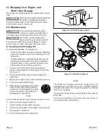
Page 35: ... dirty conditions Engine should still be warm but not hot from recent use 1 Be sure you find the correct drain plug location if present See equipment manufacturer s instructions See Figure 14 2 Disconnect spark plug wire and keep it away from spark plug 3 Make sure the gas cap is on and is tightened securely 4 Clean area around oil drain plug 5 Place approved recyclable oil container under oil dra...

Page 36: ...fingers See Figure 17 1 See III Filter Removal Installation instructions 2 Remove Air Cleaner Cover and filters See Figure 16 3 Remove debris from air inlet air cleaner cover and air intake screen 4 Inspect filter s for discoloration or dirt accumulation If either is present see Servicing Filters instructions 5 Replace Air Cleaner Cover and Filters Removing debris will insure adequate cooling corr...

Page 37: ...ct spark plug 3 Replace spark plug if porcelain is cracked or if elec trodes are Pitted Burned Fouled with deposits 4 Check electrode gap with wire feeler gauge and set gap to 030 0 76mm if necessary See Figure 18 5 Install spark plug and tighten securely NOTE A resistor spark plug must be used for replacement Contact your Authorized Tecumseh Servicing Dealer for Tecumseh Resistor Spark Plug Part ...

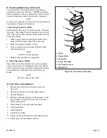
Page 38: ... NOTE DO NOT oil foam pre filter 4 Replace foam pre filter onto paper filter II Servicing Paper Filters Paper filters cannot be cleaned and must be replaced once a year or every 100 operating hours more often if used in extremely dusty conditions Replacement filters are available at an Authorized Tecumseh Servicing Dealer NOTE DO NOT clean a paper filter III Filter Removal Installation 1 Remove wi...

Page 39: ...Tecumseh recommends using UL UL UL UL ULTRA FRESH TRA FRESH TRA FRESH TRA FRESH TRA FRESH or Fuel Saver Plus Gasoline Stabilizer plus Fuel System Cleaner as acceptable methods of minimizing formation of fuel gum deposits during storage Both products are available from your Authorized Tecumseh Servicing Dealer 1 Add fuel preservative stabilizer according to manufacturer s instructions 2 Run engine ...

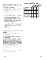
Page 40: ...ing a full arm stroke repeating once Either will distribute oil throughout the cylinder to prevent corrosion during storage 6 Install spark plug NOTE Connect spark plug wire before attempting to start engine once engine is out of storage D Battery See equipment manufacturer s instructions for proper battery storage if present IX Preventing Forest Brush and Grass Fires Local state and federal laws ...

Page 41: ... any Tecumseh Registered Service Dealer Tecumseh Authorized Service Distributor or Tecumseh Central Warehouse Distributor as soon as a problem exists The warranty repairs should be completed in a reasonable amount of time not to exceed 30 days Warranty service can be arranged by contacting either a Authorized Tecumseh Servicing Dealer or by contacting Tecumseh Products Co c o Service Manager Engin...

Page 42: ...lacement as required maintenance in the Owner s Manual shall be warranted for the period of time prior to the first scheduled replacement point for that part If the part fails prior to the first scheduled replacement the part shall be repaired or replaced by Tecumseh Products Co according to Subsection 4 below Any such emissions related part repaired or replaced under the ECS Warranty shall be war...

Page 43: ...parts and labor only the second 5 years covering parts only on electronic ignition 4 For purposes of this warranty policy consumer use shall mean consumer s personal residential household use by the original retail purchaser 5 For purposes of this warranty policy commercial use shall mean all other uses including use for commercial income producing or rental purposes 6 The engine warranty category...

Page 44: ... such as lubricants filters blade sharpening tune ups brake adjustments clutch adjustments deck adjustments and normal deterioration of the exterior finish due to use or exposure d MTD LLC does not extend any warranty for products sold or exported outside of the United States its possessions and territories except those sold through MTD LLC s authorized channels of export distribution e Parts that...

Reviews: