background image

9

Operating Tips

1.  Discharge snow downwind whenever possible. 

Slightly overlap each previously cleared path.

2.  Lifting up on the handle will allow the rubber on the 

augers to propel the snow thrower forward. Pushing 
downward on the handle will raise the augers off the 
ground and stop forward motion.

NOTE:

 Excessive upward pressure on the handle will 

result in premature wear on the rubber auger blades 
which would not be covered by warranty.
3.  Run the engine for a few minutes before stopping to 

help dry any moisture on the engine.

4.  Clean the snow thrower thoroughly after each use.

WARNING: Muffler, engine and sur-
rounding areas become hot and can 
cause a burn. Do not touch.

10. When engine starts, release starter button, and move 

choke gradually to 1/2 Choke until the engine runs 
smoothly.  Next move Choke to OFF. If engine falters, 
move choke immediately to FULL and then gradually 
to 1/2 then to OFF.

11. Disconnect the power cord. 

Always unplug from the 

outlet first, and then from the snow thrower.

Recoil Starter

1.  Move choke lever to FULL choke position (cold engine 

start).

2.  If engine is warm, place choke in OFF position instead 

of FULL.

3.  Push Primer three (3) times, making sure to cover 

vent hole when pushing. 

4.  If engine is warm, push primer button only once.

NOTE: 

Always cover vent hole in primer button when 

pushing. Additional priming may be necessary for first 
start if temperature is below 15 degrees Fahrenheit.
5.  Grasp starter handle and pull rope out slowly, until it 

pulls slightly harder. Let rope rewind slowly.

6.  Pull starter handle rapidly. Do not allow handle to snap 

back. Allow it to rewind slowly while keeping a firm 
hold on the starter handle.

7.  As engine warms up and begins to operate evenly, 

rotate choke lever slowly to the 1/2 Choke position.  
When the engine begins to run smoothly, move the 
choke to the OFF position. If engine falters, return 
to FULL choke, then slowly move to 1/2 then OFF 
position.

To Stop Engine

1.  To stop engine, turn ignition key counter-clockwise. 

Disconnect the spark plug wire from the spark plug 
to prevent accidental starting while equipment is 
unattended.

To help prevent possible freeze-up of starter, 
proceed as follows:

1.  Run engine for a few minutes before stopping to help 

dry off any moisture on the engine.

2.  Electric Starter: Connect power cord to switch box 

on engine, then to 120 volt AC receptacle. With the 
engine running, push starter button and spin the 
starter for several seconds. The unusual sound made 
by spinning the starter will not harm engine or starter. 
Disconnect the power cord from receptacle first, and 
then from switch box. 

3.  Recoil Starter: With engine running, pull starter rope with 

a rapid, continuous full arm stroke three or four times. 
Pulling the starter rope will produce a loud clattering 
sound, which is not harmful to the engine or starter.

4.  Wipe all snow and moisture from the carburetor cover 

in the area of the control levers. Also, move control 
levers back and forth several times. Leave choke 
control in the FULL choke position.

IMPORTANT: 

For complete and 

detailed engine starting, 

stopping and storing 

instructions,  

it is recommended  

that you read the 

engine manual also 

included with  

this unit .

NOTE: 

Excessive upward 

pressure on the  

handle will result in 

premature wear 

on the rubber  

auger blades which 

would not be covered 

by warranty.

5.  Remove ignition key and disconnect spark plug wire 

to prevent accidental starting. 

Operating the Snow Thrower

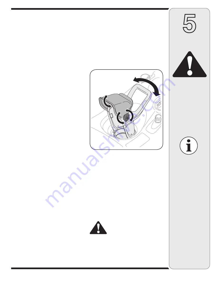
The pitch of the chute assembly controls the angle at 
which the snow is thrown. 
1.  Loosen the wing knob found on the left side of the 

chute assembly and pivot the upper chute upward or 
downward to the desired pitch. Retighten the wing 
knob before operating the snow thrower.

2.  Position the chute assembly opening by using the 

Chute Handle to throw the snow in the desired 
direction. See Figure 5-2.

Operation

WARNING: 

Muffler, engine and 

surrounding areas 

become hot and  

can cause a burn.  

Do not touch.

WARNING

Figure -

Summary of Contents for Single-Stage Snow Thrower

Page 1: ...intained in effective working order by the operator In the State of California the above is required by law Section 4442 of the California Public Resources Code Other states may have similar laws Federal laws apply on federal lands A spark arrester for the muffler is available through your nearest engine authorized service dealer or contact the service department P O Box 361131 Cleveland Ohio 4413...

Page 2: ...al White Outdoor dealer or retailer visit www whiteoutdoor com or call our Dealer Locator line at 1 800 949 4483 Engine Information The engine manufacturer is responsible for all engine related issues with regard to performance power rating specifications warranty and service Please refer to the engine manufacturer s Owner s Operator s Manual packed separately with your unit for more information B...

Page 3: ...and on the machine DANGER NEVER PUT HAND IN CHUTE CONTACT WITH ROTATING PARTS CAN AMPUTATE FINGERS AND HANDS SHUT OFF ENGINE AND WAIT UNTIL AL L MOVING PARTS HAVE STOPPED BEFORE UNCLOGGING USE CLEAN OUT TOOL OR WOODEN STICK TO UNCLOG DISCHARGE CHUTE FOR TURNING NOT LIFTING KEEP AWAY FROM RO TATING AUGER CONTACT WITH AUGER CAN AMPUTATE HANDS AND FEE T DISENGAGE CLUTCH LEVERS STOP ENGINE AND REMAIN ...

Page 4: ...e and machine adjust to outdoor temperature before starting to clear snow 9 To avoid personal injury or property damage use extreme care in handling gasoline Gasoline is extremely flammable and the vapors are explosive Serious personal injury can occur when gasoline is spilled on yourself or your clothes which can ignite Wash your skin and change clothes immediately a Use only an approved gasoline...

Page 5: ... operation regularly Refer to the maintenance and adjust ment sections of this manual 2 Before cleaning repairing or inspecting machine disen gage all control levers and stop the engine Wait until the auger impeller come to a complete stop Disconnect the spark plug wire and ground against the engine to prevent unintended starting 3 Check bolts and screws for proper tightness at frequent intervals ...

Page 6: ...igure 3 1 Assembling the Discharge Chute For shipping reasons the snow thrower has been packaged with the upper chute pivoted all the way down To pivot it upward proceed as follows NOTE Turn the chute until the chute opening is facing straight ahead 1 Remove the wing knob flat washer and carriage bolt from the lower chute See Figure 3 2 2 Pivot the upper chute upward over the lip on the lower chut...

Page 7: ...ubber paddles on the augers also aid in propelling the unit as they come in contact with the pavement Auger Control Handle Located on the upper handle the auger control handle is used to engage and disengage drive to the auger Squeeze the control handle against the upper handle to engage auger release it to disengage Discharge Chute Chute Handle Rotate the discharge chute to the left or right usin...

Page 8: ...r running Extinguish cigarettes cigars pipes and other sources of ignition The electric starter must be used with a properly grounded three prong receptacle at all times to avoid the possibility of electric shock Follow all instructions carefully prior to operating the electric starter Electric Starter if so equipped WARNING The electric starter must be used with a properly grounded three prong re...

Page 9: ...hoke then slowly move to 1 2 then OFF position To Stop Engine 1 To stop engine turn ignition key counter clockwise Disconnect the spark plug wire from the spark plug to prevent accidental starting while equipment is unattended To help prevent possible freeze up of starter proceed as follows 1 Run engine for a few minutes before stopping to help dry off any moisture on the engine 2 Electric Starter...

Page 10: ...g 3 Adjust the shave plate according to instructions above Tighten securely once adjusted NOTE Call 1 866 840 6483 for information regarding price and availability of Shave Plate Kit 753 0451 or contact the authorized Troy bilt Service Dealer in your area Control Cable As a result of both the control cable and the drive belt stretching due to wear periodic adjustments may be necessary If the auger...

Page 11: ...nder belt keeper 3 Thread belt around engine pulley 4 Push belt over bottom of auger pulley Reinstall the belt cover removed earlier Engine 1 Refer to the separate engine manual for all engine maintenance procedures 2 Check engine and snow thrower frequently for loose hardware and tighten as needed Lubrication Lubricate pivot points on the control handle and the extension spring at the end of the ...

Page 12: ... storage To avoid engine problems the fuel system should be emptied before storage for 30 days or longer Follow these instructions to prepare your snow thrower for storage WARNING Drain fuel into an approved container outdoors away from any open flame Be certain engine is cool Do not smoke Fuel left in engine during warm weather deteriorates and will cause serious starting problems 1 Remove all ga...

Page 13: ... minutes before starting 1 Move choke lever to OFF position 2 Clean fuel line and fill tank with fresh clean gasoline 3 Refer to engine manual for remedy 4 Refer to engine manual for remedy 1 Refer to engine manual for instruction 1 Firmly connect spark plug wire 2 Clear vent 1 Stop engine immediately and disconnect spark plug wire Check for possible damage Tighten all bolts and nuts Repair as nee...

Page 14: ...14 Model Series 2B5 295 18 17 55 7 32 39 40 23 24 11 3 13 47 19 21 35 41 22 28 9 31 29 30 29 4 45 43 36 33 29 38 48 27 8 1 12 2 7 44 49 34 50 46 25 6 15 26 37 20 5 10 16 9 ...

Page 15: ... Bracket Engine 1 23 790 00134 Bracket Support Gas Tank 1 24 7511152847 Primer Hose Line 4 25 7512B1476 Primer 1 REF NO PART No DESCRIPTION Qty 26 734 04204 Wheel 5 Lug Diamond Design 2 27 684 04168 Idler Pulley 1 4 hole 1 28 735 04033 Rubber Paddle 2 29 710 0896 Hex Screw 1 4 20 x 62 24 30 735 04032 Cresent Spiral 4 31 684 04228 Auger Assembly 1 32 710 0642 Hex Screw 1 4 20 x 75 Gr 5 1 33 710 065...

Page 16: ...r For parts and or accessories please call our Dealer Locator line at 1 800 949 4483 or log onto whiteoutdoor com 17 28 28 30 29 31 32 30 12 8 3 4 16 5 6 37 25 18 36 7 2 10 14 23 24 35 22 27 34 33 30 32 5 11 19 4 15 21 26 4 13 9 ...

Page 17: ...Adapter 5 Dia 1 11 725 0157 Cable Tie 1 12 732 04111 Chute Adjustment Spring 1 13 747 04159 Bail Gull Wing 1 14 749 04106 Upper Handle Gull Wing 1 15 684 0178 Mitten Grip Bracket 1 16 684 04211 Shroud Assembly Gray Incl Spark Plug Cover 1 17 710 0895 Screw 1 4 15 x 75 3 18 710 1003 Self tapping Screw 10 16 x 625 5 19 710 1090 Hex Flange Screw 5 16 18 x 1 25 2 20 710 1882 Hex Flange Screw 5 16 18 x...

Page 18: ...shave plate and hardware 753 04472 Rubber Auger Kit Snow Thrower Single Stage For parts and or accessories please call our Dealer Locator line at 1 800 949 4483 or log onto whiteoutdoor com The following accessories and kits are available for single stage two cycle snow throwers See the retailer from which you purchased your snow thrower or any authorized White Outdoor Service Dealer To find the W...

Page 19: ...19 11 NOTES Use this page to make notes and write down important information For parts and or accessories please call our Dealer Locator line at 1 800 949 4483 or log onto whiteoutdoor com ...

Page 20: ... the exterior finish due to use or exposure d Service completed by someone other than an authorized service dealer e MTD does not extend any warranty for products sold or exported outside of the United States its possessions and territories except those sold through MTD s authorized channels of export distribution f Replacement parts that are not genuine MTD parts g Transportation charges and serv...

Reviews: