background image

 4

• Only use accessories approved for this machine by

the manufacturer. Read, understand, and follow all
instructions provided with the approved accessory.

• If situations occur which are not covered by this

manual, use care and good judgment. Contact your
dealer for assistance.

2.  CHILDREN

• Tragic accidents can occur if the operator is not

alert to the presence of small children. Children are
often attracted to the tilling activity. Never assume
that children will remain where you last saw them. 

• Keep children out of the work area and under the

watchful eye of a responsible adult other than the
operator.

• Be alert and turn the unit off if a child enters the

area.

• Never allow children under the age of 14 to operate

the tiller. 

3.  SERVICE

• Use extreme care in handling gasoline and other

fuels. They are extremely flammable and the
vapors are explosive.

• Store fuel and oil in approved containers, away

from heat and open flame, and out of the reach of
children. Check and add fuel before starting the
engine. Never remove gas cap or add fuel while the
engine is running. Allow engine to cool at least two
minutes before refueling.

• Replace gasoline cap securely and wipe off any

spilled gasoline before starting the engine as it may
cause a fire or explosion.

• Extinguish all cigarettes, cigars, pipes and other

sources of ignition.

• Never refuel unit indoors because flammable

vapors will accumulate in the area.

• Never store the machine or fuel container inside

where there is an open flame or spark such as a
gas hot water heater, space heater, clothes dryer
or furnace.

• Never run your machine in an enclosed area as the

exhaust from the engine contains carbon
monoxide, which is a odorless, tasteless and
deadly poisonous gas.

• To reduce fire hazard, keep engine and muffler free

of leaves, grass, and other debris build-up. Clean
up fuel and oil spillage. Allow unit to cool at least 5
minutes before storing.

• Before cleaning, repairing, or inspecting, make

certain the tines and all moving parts have stopped.
Disconnect the spark plug wire and keep wire away
from spark plug to prevent accidental starting. Do
not use flammable solutions to clean air filter.

• Keep all nuts, bolts, and screws tight to be sure the

equipment is in safe working condition.

• Never tamper with safety devices. Check their

proper operation regularly.

• Do not alter or tamper with the engine’s governor

setting. The governor controls the maximum safe
operating speed of the engine. Overspeeding the
engine is dangerous and will cause damage to the
engine and to other moving parts of the machine. 

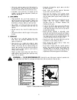
WARNING — YOUR RESPONSIBILITY: 

Restrict the use of this power machine to persons who

read, understand and follow the warnings and instructions in this manual and on the machine.

Figure 2  Safety labels found on your unit

Summary of Contents for 21A-458B190

Page 1: ...unless the engine s exhaust system is equipped with a spark arrester meeting applicable local or state laws if any If a spark arrester is used it should be maintained in effective working order by the operator In the State of California the above is required by law Section 4442 of the California Public Resources Code Other states may have similar laws Federal laws apply on federal lands A spark ar...

Page 2: ...ver The model plate will look like Figure 1 Figure 1 SECTION 2 CALLING WARRANTY SERVICE If you are having difficulty assembling this product or if you have any question regarding the controls operation or maintenance of this unit please call the Customer Dealer Referral Line You can reach them by calling 1 800 949 4483 Before calling your local dealer make sure that you have your model and serial ...

Page 3: ...ller while under the influence of alcohol or drugs Keep the area of operation clear of all persons particularly small children and pets Stop the engine when they are in the vicinity of your tiller Wear sturdy rough soled work shoes and close fitting slacks and shirt Shirt and slacks that cover the arms and legs and steel toed shoes are recommended Do not wear loose fitting clothes or jewelry and s...

Page 4: ...rs pipes and other sources of ignition Never refuel unit indoors because flammable vapors will accumulate in the area Never store the machine or fuel container inside where there is an open flame or spark such as a gas hot water heater space heater clothes dryer or furnace Never run your machine in an enclosed area as the exhaust from the engine contains carbon monoxide which is a odorless tastele...

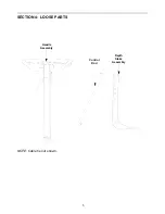
Page 5: ...5 SECTION 4 LOOSE PARTS Handle Assembly Depth Stake Assembly Control Rod NOTE Cable tie not shown ...

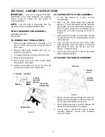
Page 6: ... the tine shield hinge flap assembly Remove T knob flat washer and hex bolt from depth stake Insert the depth stake assembly in front of spacer under the tine shield and up through the tine shield assembly as shown in Figure 3 3 Insert clevis pin through the tine shield and the second hole from top of the depth stake Secure with hairpin clip 4 Insert hex bolt into the top hole of the depth stake a...

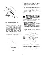
Page 7: ...ueeze the clutch control bail against the handle The control wire should now be straight NOTE Do not overtighten control wire Too much tension may cause it to break WARNING Be certain to check the clutch cable adjustment as instructed on page 7 of your owner s guide before operating the tiller Secure drive cable to handle using cable tie Refer to Figure 8 Cut off excess end of cable tie ATTACHING ...

Page 8: ...acturer s recommended pressure WARNING Maximum tire pressure under any circumstances is 30 p s i Equal tire pressure should be maintained on both tires SECTION 6 CONTROLS Figure 8 THROTTLE CONTROL The throttle control lever is located on the engine It controls the engine speed and stops the engine See Engine manual for further information CHOKE LEVER The choke lever is located to the left of the t...

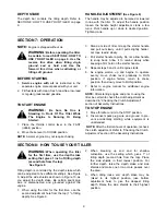
Page 9: ...adually to RUN position If engine falters return to choke position then slowly move to RUN position 7 Refer to engine manual for additional engine information NOTE After starting engine and prior to using the tiller be certain to check the clutch adjustment as described in Checking the Clutch Adjustment section of Assembly Instructions TO STOP ENGINE 1 Move throttle control to the STOP position 2 ...

Page 10: ...r selection 4 Squeeze the clutch control bail against the handle to engage the wheels and tines NOTE Make certain the gear selection indicator is correctly positioned before engaging the clutch handle If it is between gears the engine will stall To transport tiller do not engage the tines Select the wheel drive only WARNING Do not push down on the handles so that the wheels are lifted off the grou...

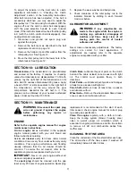
Page 11: ...ansmission all the way around the gear compartment Assemble the left half to it This grease can be obtained at your nearest authorized dealer Order part number 737 0300 Clutch Bail Lubricate the pivot point on the clutch bail and the cable at least once a season with light oil The control must operate freely in both directions Pivot Points Lubricate all pivot points and linkages at least once a se...

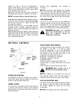
Page 12: ...pulley by removing two hex bolts and lock washers See Figure 12 5 Remove belt Reassemble new belt following instructions in reverse order Figure 11 NOTE Upon reassembly make certain the belt is routed over the idler pulley and inside of belt keepers by engine pulley See Figure 12 Figure 12 TIRES Recommended operating tire pressure is approximately 20 p s i check sidewall of tire for tire manufactu...

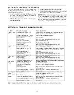
Page 13: ...ngine runs erratic Unit running on CHOKE Spark plug wire loose Blocked fuel line or stale fuel Vent in gas cap plugged Water or dirt in fuel system Dirty air cleaner Carburetor out of adjustment Move choke lever to OFF position Connect and tighten spark plug wire Clean fuel line fill tank with clean fresh gasoline Fuel will not last over thirty days unless a fuel stabilizer is used Clear vent Drai...

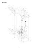
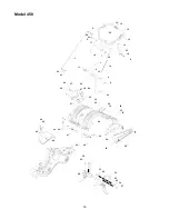
Page 14: ...14 Model 458 ...
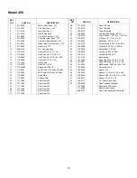
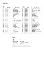
Page 15: ...ar 30T 25 717 1585 Spur Gear 44T 26 717 1587 Spur Gear 44T 27 717 1594 Spur Gear 16T 28 721 0378 Seal 1 0 Shaft 29 721 0379 Seal 75 Shaft 31 726 0277 Taper Cap Ring 32 732 0496 Compression Spring 50 Lg 33 736 0163 Thrust Wash 1 03 I D x 1 62 O D 34 736 0351 Fl Wash 76 I D x 1 5 O D 35 736 0407 Bell Wash 45 I D x 1 0 36 736 0518 Thrust Wash 445 x 1 92 x 060 37 736 3088 Fl Wash 635 I D x 1 59 O D 40...

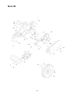
Page 16: ...odel 458 12 15 12 12 22 2 60 61 5 17 19 1 60 61 11 6 16 14 4 9 3 7 20 8 18 10 23 37 34 62 25 27 64 30 39 26 63 32 36 33 31 27 29 26 41 42 46 44 49 44 26 40 30 24 35 28 21 50 59 58 51 65 53 55 56 54 57 30 38 ...

Page 17: ...5 16 18 x 75 Lg 33 747 0432 Rod 34 750 0885 Spacer 435 O D x 322 I D 35 786 0090 Shoulder 36 786 0113 Tine Shield Hinge Flap 37 786 0176 R H Handle Brkt 38 786 0177 L H Handle Brkt 39 786 0178 Tine Shield 40 786 0179 Tine Shield Brkt 41 786 0180 Shoulder Spacer Brkt 42 686 0109 Shift Crank Ass y 44 710 1017 Screw 1 4 14 x 625 46 715 0120 Spirol Pin 3 16 x 1 00 49 784 0208C Shift Cover 50 711 0415 ...

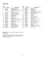
Page 18: ...18 Model 458 18 17 24 19 27 46 45 12 26 9 6 1 8 25 14 28 20 2 11 44 4 22 23 16 5 21 7 13 15 3 40 43 42 41 39 32 33 31 30 29 36 34 37 37 38 35 10 ...

Page 19: ...Half 24 756 1162 Input Pulley 25 786 0064A Idler Bracket 26 786 0186 Belt Keeper Brkt 27 786 0123A Shift Cover Brkt 28 786 0193 Idler Belt Keeper 29 634 0106 RH Wheel Ass y Comp 16 0 x 4 0 634 0107 LH Wheel Ass y Comp 16 0 x 4 0 734 0808 Tire Only 16 0 x 4 0 30 634 0108 Wheel Rim Ass y Comp 31 734 0255 Air Valve 32 711 1017 Clevis Pin 33 714 0104 Internal Cotter Pin 34 710 0382 Hex Bolt 1 2 13 x 5...

Page 20: ...oor Products Company TRANSPORTATION CHARGES Transportation charges for the movement of any power equipment unit or attachment are the responsibility of the purchaser Transportation charges for any parts submitted for replacement under this warranty must be paid by the purchaser unless such return is requested by White Outdoor Products Company UNITS EXPORTED OUT OF THE UNITED STATES White Outdoor P...

Reviews: