47
Chapter 5 DFX
™
Pro Options
25. D.C. Phase
Measurement of the ground mineralization, or
measuring the phase (V.D.I. reference number) of a
specific metal target during pinpointing.
When D.C. PHASE is ON, and the TRIGGER
squeezed and released, normal searching begins.
When a target is located, or when the operator
wants to measure a target or the ground, the TRIG-
GER is squeezed and held as if to pinpoint. When
the loop is held stationary over the target or ground,
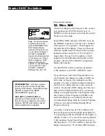
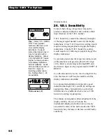
the D.C. PHASE is shown on the upper-right side
of the display. The depth reading can be used to
help center the loop over a target for more accurate
indications. The audio tone will also assist in
centering the loop over the target.
Metal targets in the ground will produce a measure-
ment which represents the target indication
±
the
ground measurement. To measure the target alone,
move the loop off to one side (being sure to hold
the loop directly on top of the ground mineral), and
release and re-squeeze the trigger. Then move the
loop back over the target. This should allow a
proper D.C. PHASE reading for the target alone.
The relationship between D.C. PHASE, Ground
Balance, V.D.I. number and Discrimination is
complex. Results are not always repeatable in
varied ground conditions. Ground and target re-
sponses can distort the detection field of the loop in
a number of ways, by bending, reflecting, absorbing
and thus altering the phase and amplitude the
detector measures. This in turn produces inconsis-
tencies in the relationships of these features.
When considering specific numbers it is important
to know D.C. phase is provided by the 15 kHz
channel without normalization. The V.D.I. scale is
distorted/expanded in the lower end of the scale
(foil/nickel) and compressed in te higher end of the
scale (copper/silver).
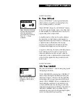
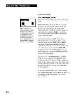
D.C. PHASE
ON
OFF
TO CHANGE PRESS
ENTER
(Display section)
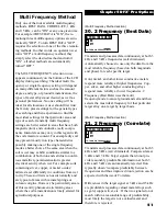
Tips - In specific ground
conditions, certain Basic
Adjustments and Pro
Options may produce
better performance. By
measuring the ground and
taking notes, such condi-
tions may also be recog-
nized in other areas and
dealt with by using similar
settings.
10.5"
+ - 1 2 - + - + - 9 - + - + - 6 - + - + - 3 - + - + - 0
-82.2
The D.C. Phase of the ground has a relationship
to the proper Ground Balance setting. This is of
particular interest to those who use the optional
COARSE or FINE G.E.B. (Manual Ground
Balance). Manual Ground Balance has a range
that covers V.D.I. numbers from -95 - +10. A
Manual Ground Balance Coarse setting of 0
equals a D.C. PHASE of negative -95. A Coarse
setting of 255 equals a D.C. Phase of +10. As
mentioned under COARSE and FINE G.E.B.,
Ground Balance is not the same as EDITing
these V.D.I. numbers for REJECT. However, if
your ground measures -90, ACCEPTing
V.D.I. -90 will produce operational problems as
the detector will see the ground as a target. With
the same logic, if a target measures -90, and the
ground measures -90, and the detector is Ground
Balanced to this -90 ground, such a target will be
virtually invisible to the detector. These conditions
would be extremely rare however; the point is
there must be a difference between the target and
the ground for the target to be detected.

