PLANNING YOUR INSTALLATION
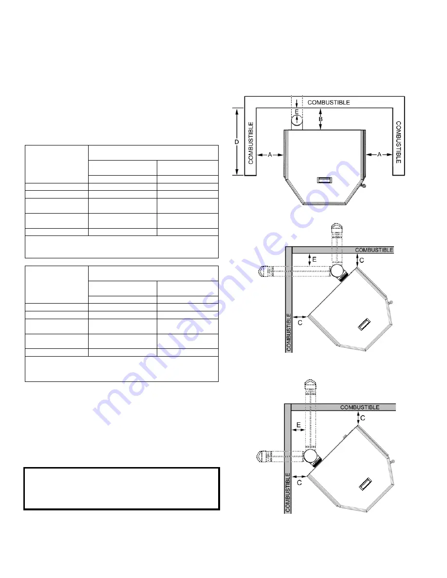
Clearances to combustibles are determined from testing to applicable standards for allow-
able heat transfer. The clearances allowed as shown here, do not take into account opera-
tion or serviceability requirements.
PAGE 7
CLEARANCES
Optima
2 FS and Optima 3 FS
- Standard residential or
manufactured (mobile) home installation. These appli-
ances require the following minimum clearances to com-
bustibles:
MINIMUM CLEARANCES TO COMBUSTIBLES
Manufactured (Mobile) Home
or Residential Installation
Horizontal Flue – Di-
rectly Through Wall
Interior Vertical Flue
Optima 2 FS
Clearance to
Combustibles
inch / millimeter
inch / millimeter
A - Sidewall to unit
♦
4”
/ 102 mm
♦
4”
/ 102 mm
B – Backwall to unit
*2” / 51 mm
9” / 229 mm
C – Sidewall to unit
Corner
*2” / 51 mm
*2” / 51 mm
D – Max. Depth of
Alcove
•
24” / 610 mm
•
24” / 610 mm
E – Flue to Wall
3” / 77 mm
3” / 77 mm
♦
Measured to fuel hopper lid in alcove.
•
Minimum Alcove Measurements - Height 48” / 1220 mm
Width 31” / 788 mm
Manufactured (Mobile) Home
or Residential Installation
Horizontal Flue – Di-
rectly Through Wall
Interior Vertical Flue
Optima
3 FS
▪
Clearance to
Combustibles
inch / millimeter
inch / millimeter
A - Sidewall to unit
♦
6”
/ 153 mm
♦
6”
/ 153 mm
B – Backwall to unit
*2” / 51 mm
9” / 229 mm
C – Sidewall to unit
Corner
*2” / 51 mm
*2” / 51 mm
D – Max. Depth of
Alcove
•
16” / 407 mm
•
16” / 407 mm
E – Flue to Wall
3” / 77 mm
3” / 77 mm
♦
Measured to fuel hopper in alcove.
•
Minimum alcove measurements - Height 48” / 1220 mm
Width 38” / 966 mm
Minimum clearances specified may not allow for
ease of operation and maintenance (please take
this in to account when planning the installation).
If installed to the minimum clearances, removal of
the appliance may be necessary for servicing.
Recommended clearance zone from the front of
the appliance to combustibles is 4 feet minimum.
* The certified back wall clearance as shown on the
listing label is 1" (see Safety / Listing Label) but for
proper hopper lid operation in corner and parallel
installations a 2" clearance is required.
Rear Wall or Alcove – Optima
2 FS and Optima 3 FS
Corner - Optima 2 FS
Corner - Optima 3 FS
*
*
*
*
*
Summary of Contents for Advantage Optima 2 FS
Page 38: ...WIRING DIAGRAM PAGE 38 ...
Page 44: ...REPLACEMENT PARTS DIAGRAMS PAGE 44 5 6 8 10 13 14 9 12 7 11 ...
Page 45: ...REPLACEMENT PARTS DIAGRAMS PAGE 45 15 16 17 19 20 22 24 25 26 27 18 23 ...
Page 46: ...REPLACEMENT PARTS DIAGRAMS PAGE 46 30 37 38 40 41 29 28 33 34 39 31 32 35 ...
Page 47: ...REPLACEMENT PARTS DIAGRAMS PAGE 47 43 44 45 46 47 42 ...
Page 49: ...INSTALLATION TIPS PAGE 49 ...


