background image


P.O. Box 2827 
Eugene, OR 97402 USA


Production Code: 


VN 

05/17 


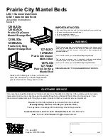
Prairie City Mantel Beds 

LSO = Summer Oak finish 
DAO = Autumn Oak finish
 
Assembly Instructions 

Model #


IMPORTANT NOTES: 

  For normal household use only. 

Not

 recommended for commercial use. 

  Remove items before you move this unit. 

  Do not overload the drawers. 

  This assembly requires two people.


WARNING


Drilling, sawing, sanding or machining wood products can expose you to 
wood dust, a substance known to the state of California to cause cancer. 
Avoid  inhaling wood dust or use a dust mask or other safeguards for 
personal protection.


For more information go to: www.p65warnings.ca.gov/wood


This product can expose you to chemicals, including formaldehyde, 
which are known to the State of California to cause cancer.


For more information go to: www.p65warnings.ca.gov/furniture 


DESIGN SUBJECT TO CHANGE WITHOUT NOTICE.


CUSTOMER SERVICE


If you ever have questions about your furniture, please do not hesitate to contact us. In the unlikely event you need a 
replacement part; we can make those parts available through an authorized Whittier Wood Furniture dealer. If you 
cannot order replacement parts through your dealer, please contact our customer service department. 

Hours:

 Our friendly customer service staff can be reached: 

Monday-Friday 8:00 a.m. to 5:00 p.m. (Pacific Time)

You may leave a message 24 hours a day, seven days a week. 

Customer Service: 

800-653-3336 • 

Outside the U.S.: 

541-687-0213 


Fax:

 541-687-2060• 

Email:

 info@whittierwood.com


1254LSOc 
1254DAOc


Prairie City Queen  
Mantel Storage Bed


1259LSOc 
1259DAOc


Prairie City King  
Mantel Storage Bed


1274LSO 

1274DAO


Prairie City Queen  

Mantel Bed


1277LSO 

1277DAO


Prairie City King  

Mantel Bed


Thank you for allowing us to help you furnish your 
home. We are certain you will be delighted with 
your new furniture for many years to come.  


Summary of Contents for 1254DAOc

Page 1: ... furniture DESIGN SUBJECT TO CHANGE WITHOUT NOTICE CUSTOMER SERVICE If you ever have questions about your furniture please do not hesitate to contact us In the unlikely event you need a replacement part we can make those parts available through an authorized Whittier Wood Furniture dealer If you cannot order replacement parts through your dealer please contact our customer service department Hours...

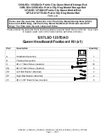
Page 2: ... this list If you need to replace a part refer to the model number part letter and name 1257LSO 1257DAO Queen Headboard Footboard Kit x1 Part Description Quantity A Headboard Assembly 1 B Footboard Assembly 1 U 8 x 1 Black Screw inserted 16 ZN 8 x 2 Black Screw inserted 4 ZO Left Bed Bracket attached 2 ZP Right Bed Bracket attached 2 ZV 8 x 1 5 8 Black Screw inserted 8 Please note this Assembly In...

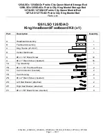
Page 3: ...SO_1277DAO Page 3 05 17 1261LSO 1261DAO King Headboard Footboard Kit x1 Part Description Quantity A Headboard Assembly 1 B Footboard Assembly 1 C King Trestle 27 9 16 4 D Center Deckboard 1 S 8 x 1 1 4 Black Screw 12 U 8 x 1 Black Screw inserted 16 YA Top Assembly 1 YB 8 x 1 1 4 Pan Head Screw 2 YC Cam Connector inserted 2 YD Cam Housing 2 ZN 8 x 2 Black Screw inserted 4 ZO Left Bed Bracket attach...

Page 4: ...ox assembled 1 H Drawer Face attached 3 I Queen Trestle 11 9 16 2 J Left Right Center Deckboard 1 K Notched Deckboard attached 1 L Assembled Foot 3 M Long Angle Iron attached 1 N 20 Drawer Slides pre installed sets 3 O 6 x 3 4 Philtruss Screw inserted 18 P 6 x 3 4 Flat Head Screw inserted 10 Q 6 x 1 2 Philtruss Screw 22 18 inserted Ra 8 x 7 8 Black Lo Profile Screw inserted 18 S 8 x 1 1 4 Black Sc...

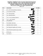
Page 5: ...DAOc_1274LSO_1274DAO_1277LSO_1277DAO Page 5 05 17 Part Description Quantity YE 10 x 3 4 Pan Head Screw inserted 12 ZA 1 4 Hex Nut inserted 4 ZB 1 4 T Nut inserted 2 ZC 1 4 x 80mm Hex Bolt 1 ZD 1 4 x 2 1 2 Hex Bolt inserted 4 ZE 1 4 x 1 3 4 Hex Bolt 6 ZF Pull attached 3 ZH Foot Bracket attached 3 ZI Adjustable Glide installed 3 ZJ Left Pedestal Angle Bracket inserted 1 ZK Right Pedestal Angle Brack...

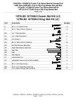
Page 6: ...DAO Queen Rail Kit x1 1278LSO 1278DAO King Rail Kit x1 Part Description Quantity S 8 x 1 1 4 Black Screw 10 U 8 x 1 Black Screw inserted 16 ZB 1 4 T Nut inserted 9 ZC 1 4 x 80mm Hex Bolt 2 ZM Hex Wrench 1 ZN 8 x 2 Black Screw inserted 22 ZO Left Bed Bracket attached 2 ZP Right Bed Bracket attached 2 ZQ Side Rail 2 ZR Slat 5 ZS Slat Support 2 ZT Assembled Foot 4 ZU Adjustable Glide with Hex Nut ins...

Page 7: ...ch provided Phillips screwdriver Slotted screwdriver 1 2 7 16 open end or box end wrench and Tape measure Notes Steps 1 through 14 are for the Prairie City Queen Mantel Storage Bed 1254 and the Prairie City King Mantel Storage Bed 1259 Steps 15 through 25 are for the Prairie City Queen Mantel Bed 1274 and the Prairie City King Mantel Bed 1277 Steps 1 2 3 are for the Prairie City King Mantel Storag...

Page 8: ...EFORE YOU BEGIN THE FOLLOWING STEP Insert Cam Housings YD into the two pre drilled holes on the Headboard Assembly A as shown in Figure 2 Lower Top Assembly YA so that the Cam Connectors YC fit into the housings YD tighten the cam housings as indicated in the Cam lock System instructions See Figures 2 and 2a 3 Attach the Top Assembly YA to the Headboard Assembly A by inserting two 8x1 1 4 Pan Head...

Page 9: ...y requires two people 1254LSOc_1254DAOc_1259LSOc_1259DAOc_1274LSO_1274DAO_1277LSO_1277DAO Page 9 05 17 4 Place both Pedestals Ea approximately 63 apart for 1254 Queen Bed or 79 apart for 1259 King Bed as shown in Figures 4 and 4a 5 To attach the Footboard B to the Pedestal Ea align the Brackets and slide the Pedestal down on to the Footboard B See Figures 5 and 5a Fig 5 Ea B Fig 5a Fig 4 63 For 12...

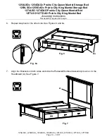
Page 10: ...DAO Prairie City King Mantel Bed Assembly Instructions This assembly requires two people 1254LSOc_1254DAOc_1259LSOc_1259DAOc_1274LSO_1274DAO_1277LSO_1277DAO Page 10 05 17 6 Repeat step five for the other side See Figures 6 and 6a 7 Align the Brackets on both sides and slide the Pedestal Footboard assembly down on to the Headboard A See Figure 7 Fig 7 A Fig 6 Ea Fig 6a ...

Page 11: ... There are blocks mounted on the back side of the Footboard to support the end of the pedestal eliminating the need for an Assembled Foot in this position where it would be easily visible Do not attach an Assembled Foot in the position near the footboard Align three Assembled Feet L over the insert nuts that are on the back of the Pedestal Make sure the Adjustable Glides are on the outside face of...

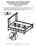
Page 12: ...254LSOc_1254DAOc_1259LSOc_1259DAOc_1274LSO_1274DAO_1277LSO_1277DAO Page 12 05 17 9 Repeat by attaching three additional Assembled Feet L to the other Pedestal with 1 4 x 1 3 4 Hex Bolts ZE and 1 4 Flat Washers W See Figures 9 and 9a Using a 1 2 wrench or Slotted screwdriver adjust the Adjustable Glides ZI on the bottoms of the Assembled Feet L so that the top surfaces of both Pedestal decks are 16...

Page 13: ...requires two people 1254LSOc_1254DAOc_1259LSOc_1259DAOc_1274LSO_1274DAO_1277LSO_1277DAO Page 13 05 17 10 Facing the Footboard attach the Pedestal Assembly to the Footboard with a 90º Bracket ZL and four 6 x 1 2 Philtruss Screws Q Repeat for the other side See Figures 10 and 10a Using the Hex Wrench ZM attach the Headboard to the Pedestals with two 1 4 x 80mm Hex Bolts ZC See Figure 10 Fig 10 Fig 1...

Page 14: ...necessary readjust the glides at the bottom of the Assembled Feet so that all are touching the floor and support weight Place the four Queen Trestles I or King Trestles C into the bed assembly as shown in Figures 11 and 11a If you have purchased a 1259 King storage bed Recycle discard the Queen bed trestles that were include with your pedestals IMPORTANT the center two trestles nest into the notch...

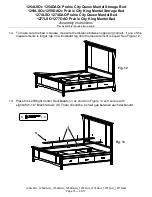
Page 15: ...ple 1254LSOc_1254DAOc_1259LSOc_1259DAOc_1274LSO_1274DAO_1277LSO_1277DAO Page 15 05 17 12 To make sure the bed is square measure the distance between opposing corners If one of the measurements is larger tap on a footboard leg until the measurement is equal See Figure 12 13 Place the Left Right Center Deckboards J as shown in Figure 13 and secure with eight 8x1 1 4 Black Screws S There should be a ...

Page 16: ...74LSO_1274DAO_1277LSO_1277DAO Page 16 05 17 Step 14 is for the Prairie King Mantel Storage Bed 1259 14 Place the Center Deckboard D as shown in Figure 14 and secure with twelve 8 x 1 1 4 Black Screws S If you need to adjust the Assembled Feet remove the Center Deckboard adjust the glides and reattach the deckboard This concludes the assembly process for Prairie City Storage Bed if you have purchas...

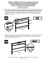
Page 17: ...ard Footboard kit contains a Center Deckboard D and King Trestles C that are used for a storage bed option remove these parts from the back of the Headboard A and discard or recycle them See Figure 15 16 NOTE READ CAM INSTRUCTIONS NOW BEFORE YOU BEGIN THE FOLLOWING STEP Insert Cam Housings YD into the two pre drilled holes on the Headboard Assembly A as shown in Figure 16 Lower Top Assembly YA so ...

Page 18: ...17 17 Attach the Top Assembly YA to the Headboard Assembly A by inserting two 8x1 1 4 Pan Head Screws YB into the predrilled holes in the block that is attached to the Headboard Assembly A See Figures 17 and 17a 18 Position the two Slat Support ZS over the blocks that are mounted onto back side of the Footboard B and attach with four 8 x 1 5 8 Black Screws ZV through the predrilled holes in the sl...

Page 19: ...antel Bed Assembly Instructions This assembly requires two people 1254LSOc_1254DAOc_1259LSOc_1259DAOc_1274LSO_1274DAO_1277LSO_1277DAO Page 19 05 17 19 To attach the Footboard B to the Side Rail ZQ align the Brackets and slide the Side Rail down on to the Footboard B See Figures 19 and 19a 20 Repeat step nineteen for the other side See Figures 20 and 20a Fig 20 ZQ Fig 20a Fig 19 ZQ B Fig 19a ...

Page 20: ...Assembly Instructions This assembly requires two people 1254LSOc_1254DAOc_1259LSOc_1259DAOc_1274LSO_1274DAO_1277LSO_1277DAO Page 20 05 17 21 Align the Brackets on both sides and slide the Side Rail Footboard assembly down on to the Headboard A See Figure 21 22 Using the Hex Wrench ZM attach the Headboard to the Side Rails with two 1 4 x 80mm Hex Bolts ZC See Figure 22 Fig 22 ZC ZC x 2 ZM x 1 Fig 2...

Page 21: ...17 23 Attach an Assembled Foot ZT to four of the five Slats ZR as shown in Figure 23 24 Move the bed assembly to its final position Position the Slats ZR on the bottom edges of the rails and place the slat without the Assembled Foot nearest to the Footboard Attach with 8 x 1 1 4 Black Screws S See Figure 24 25 Adjust the Adjustable Glides with Hex Nut ZU on the Assembled Feet ZT so the Glides just...

Page 22: ... TURN the Cam Housing clockwise at LEAST 1 4 turn to the 9 00 position Turning the Cam Housing between 1 4 and 1 2 turn should be enough to ensure rigid tension Tension should be initiated as soon as 10 00 You should receive optimum tightness at 11 00 IF this does not occur tighten or loosen the Cam Connector to achieve proper tension 2 You may need extra tension if A The Cam Connector was screwed...

Reviews: