InstallatIon · Manual
4. Cable connection, sealing compound
and maintenance
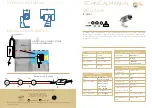
Open the connection unit on the back of the spotlight, guide the cable
through the cable fitting on the spotlight, adapt the seal insert to the
outside diameter of the cable, connect it to the connection terminals in ac-
cordance with the connection diagram, screw on the tension relief, seal the
cable fitting and seal the complete connection unit with sealing compound
9.9011.00.25. After that, screw the cover with seal back on tight.
3.11.
note:
Sealing compound 9.9011.00.25 sufficient for 2 spotlights. Please
order separately.
Soiling and deposits on glass or stainless steel parts must be removed with
standard cleaning agents.
4. Raccordement du câble, scellement
et maintenance
Ouvrir l‘unité de raccordement au dos du projecteur, amener le câble
jusqu‘au projecteur par le raccord du câble, adapter la garniture d‘étanchéité
en fonction du diamètre extérieur du câble, faire le raccord aux bornes de
branchement suivant le plan de connexions, visser la pince de décharge de
traction, visser les raccords du câble et sceller toute l‘unité de raccordement
avec le masse de scellement 9.9011.00.25. Revisser ensuite le couvercle à
bloc avec le joint.
3.11.
Remarque:
Masse de scellement 9.9011.00.25 suffisant pour 2
projecteurs. A commander séparément.
Les impuretés et les dépôts sur le verre ou les pièces en acier inoxydable
doivent être éliminés à l‘aide d‘un détergent classique.
WIBRE Elektrogeräte Edmund Breuninger GmbH & Co. KG · Liebigstrasse 9 · 74211 Leingarten/Germany
Telefon: +49 (0) 7131 9053-0 · Telefax: +49 (0) 7131 9053-19 · E-Mail: info@wibre.de
4
/6
4. Kabelanschluß, Verguß und Wartung
Am Scheinwerfer rückseitig die Anschlußeinheit öffnen, das
Kabel durch die Kabelverschraubung am Scheinwerfer einfüh-
ren, Dichteinsatz entsprechend des Aussendurchmessers des
Kabels anpassen, an den Anschlussklemmen laut Anschlussbild
anschließen, Zugentlastung anschrauben, die Kabelverschraubung
verschließen und die komplette Anschlusseinheit mit Vergußmaße
9.9011.00.25 vergießen. Danach den Deckel mit Dichtung wieder
fest verschrauben.
3.11.
Hinweis:
Vergußmasse 9.9011.00.25 ausreichend für 2 Schein-
werfer. Bitte separat bestellen.
Verunreinigungen und Ablagerungen auf Glas oder Edelstahlteilen
sind mit handelsüblichen Reinigungsmitteln zu entfernen.
Deckel
Cover
Couvercle
Schraube
Screw
Vis
Anschlußeinheit
Connection Unity
Raccordement
Zugentlastung
Cable anchorage
Décharge de traction
Dichteinsatz
Seal insert
Joint
Überwurfmutter
Cap nut
Écrou
– +
Dichtung
Seal
Joint
Auffüllen Vergußhöhe
Height of filling
Niveau de scellement
Verguß
Sealing
Scellement
M
ischb
eut
el
M
ixing bag
sac mélangeur
3.11
achtung:
Anschluss der Netzteile muss stromlos erfolgen,
da sonst Entladungen im Netzteil zur Schädigung der LED führen
können. Es darf keine Primärspannung anliegen.
achtung:
Werden weniger als 4 Scheinwerfer angeschlossen, ist
die Reihenfolge der Ausgangskanäle zu beachten, beim Anschluss
von nur 3 Scheinwerfern werden also die Kanäle 1 bis 3 benutzt, bei
2 Scheinwerfern die Kanäle 1 bis 2 und so weiter.
Hinweis:
Die Installation eines bauseitigen Überspannungsschutzes
nach DIN VDE 0100-443, DIN VDE 0100-534 und EN 62305 wird empfohlen.
attention:
The power supply must be connected without power,
since otherwise discharges in the power supply unit may damage
the LED. Primary voltage must not be present.
attention:
If less than 4 spotlights are connected, the sequence
of the output channels must be observed; if only 3 spotlights are
connected, channels 1 to 3 are used, if 2 spotlights are connected
channels 1 to 2 are used, and so on.
note:
Installation of customised surge protection in accordance with
DIN VDE 0100-443, DIN VDE 0100-534 and EN 62305 is recommended.
attention:
Les blocs d‘alimentation doivent être raccordés hors ten-
sion, sinon des décharges dans le bloc d‘alimentation peuvent détériorer
les LED. Aucune tension primaire ne doit être présente.
attention:
Si on raccorde moins de 4 projecteurs, il faut suivre l‘ordre
des canaux de sortie. Si on raccorde seulement 3 projecteurs, on utilise par
conséquent les canaux 1 à 3, 2 projecteurs les canaux 1 à 2 et ainsi de suite.
Remarque:
L‘installation d‘un système anti-surtension local
conforme aux normes DIN VDE 0100-443, DIN VDE 0100-534 et EN 62305
est recommandée.
max 40 m
5.0670.12.72
prim
230 V
dimm
dimm
1
2
3.9
achtung:
Ein Montageabstand von 10 cm zwischen Betriebs-
geräten wird dringend empfohlen, um wechselseitiges Erhitzen zu
vermeiden.
Hinweis:
Nur Edelstahlwerkzeug verwenden!
Zur Vermeidung von Fremdrost!
attention:
A mounting distance of 10 cm between various
power supplies is strongly recommended, in order to avoid mutual
heating.
note:
Only use tools made of stainless steel!
To avoid extraneous rust!
attention:
Une distance de montage de 10 cm entre plusieurs
alimentations est vivement conseillé pour éviter une chauffe
mutuelle !
Remarque:
L‘utilisation d‘outils en acier inoxydable est obliga-
toire! Pour éviter que la corrosion se forme!