background image


INSTALLATION PROCEDURE 


9. UNPACKING 


The Water heater is  supplied in a separate carton. Care should be taken when unpacking to ensure there is no 

damage to the product. 


Included in the Water heater carton are: Installation and User instructions, Gas isolation valve & 100mm of 15mm dia 

Copper tube + flue clamping collar and sealing ring. 

In a separate pack: Flue kit – comprising of Inlet and outlet rigid tube – Terminal – Elbow  - Clamping Ring & Sealing 

Collar.  

THE WATER HEATER MUST BE INSTALLED WITH THE SUPPLIED FLUE KIT  


10. SELECTING THE POSITION 

Decide where the heater is to be fixed taking into account the installation requirements required under the relevant 

standards and sections 1, 2,3,12 of these instructions. 


11. WALL MOUNTING 

The Water Heater can either be mounted with the flue system exiting to the rear or side of the appliance. For 

Wall mounting with flue to the rear refer to paragraph entitled ‘Flue installation to the rear’. 


Materials around the flue system –  The outer flue  will reach a maximum 

temperature rise of 35

o

C. Care should be taken in ensuring that any materials 

touching the outer flue are capable of withstanding this temperature for extended 

periods. It is recommended that the rubber inner and outer seals are pushed into 

the wall aperture before sealing. This will ensure that the outer flue pipe fits 

centrally in the wall aperture. 


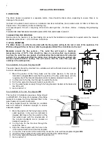
Flue installation to the side: See diagram 

Bi


The water heater should be mounted on a suitable wall with sufficient structural strength 

to ensure adequate support.  


1.  Mark the position of the fixing holes and the outlet aperture in the wall as 

indicated in diagram 

Bi

. Ensure that the position of the flue outlet meets with the 

requirements of the relevant standards and is located as detailed in section 2. 

2.  Cut the hole for the flue liner through the wall of the home. 

3.  Fix the flue system to the water heater see section 12. 

4.  Fix the water heater securely through the fixing brackets located at the base and 

top of the unit. 

5.  Go to section 12. 


Flue installation to the rear: See diagram 

Biii


This method of installation requires a fixing kit part 

no. RSWFIX01. The fixing kit comprises of two fixing 

brackets to replace the fixing brackets fitted to the 

water heater and a wall closure plate. 

The water heater should be mounted on a suitable 

wall with sufficient structural strength to ensure 

adequate support.  


1.  Mark the position of the fixing holes and the 

outlet aperture in the wall as indicated in 

diagram 

Bi

.  Ensure that the position of the 

flue outlet meets with the requirements of 

the relevant standards and is located as 

detailed in section 2. 

2.  Cut the hole for the flue liner through the 

wall of the home. 

3.  Align the closure plate with the hole in the 

inner wall and mark around the closure plate. 

4.  Cut out the inner section of the wall to fully recess the inner wall closure plate diagram 

Biii

5.  Insert the closure plate into the wall opening and fix with suitable fixings. 

6.  Fix the flue system to the water heater see section 12. 

7.  Go to section 12. 


Summary of Contents for JSG12ST-S25

Page 1: ...It should also be in accordance with the relevant recommendations in the current editions of all relevant National Standards Your particular attention is drawn to the following standards relevant to a...

Page 2: ...ed so that they cannot be touched by the person using the bath or shower Your attention is drawn to the current IEE Wiring Regulations and in Scotland the electrical provisions of the Building Regulat...

Page 3: ...connection 6 GAS SUPPLY The gas pipes must be copper Do not connect plastic pipes directly to the heater It is recommended that the copper is extended to below the floor of the caravan vehicle before...

Page 4: ...side flue configuration 345 565 175 60 100 25 77 130 180 594 JSG12ST S25 rear flue configuration 345 565 205 60 100 25 107 130 180 594 J water in K gas in L water out M N O P Q WEIGHT 80 62 100 170 10...

Page 5: ...heater should be mounted on a suitable wall with sufficient structural strength to ensure adequate support 1 Mark the position of the fixing holes and the outlet aperture in the wall as indicated in d...

Page 6: ...ture for replacement part numbers NOTE The inner flue pipe of the terminal must be cut accurately and must always be 100 mm longer than the outer flue in order to ensure correct location in the termin...

Page 7: ...e diagram Eiv 8 Fit the water heater to the wall by inserting the flue pipe through the hole in the wall and securing the water heater through the fixing brackets into the pre drilled holes as detaile...

Page 8: ...go to a none illuminated condition Push the power symbol on the front panel The control panel will light up and display the temperature setting of the water supplied This temperature can be adjusted...

Page 9: ...flow rate through the water heater The flow rate of the hot water is controlled by the hot outlet tap shower The water heater can theoretically supply more than one outlet simultaneously however in pr...

Page 10: ...ce gas supply bottle 12 Flame outage Switch off mains power supply Check mains supply and fuse Restart by switching mains supply on and pressing the on off button on the control panel If problem persi...

Page 11: ...iance and consult your installer or service engineer If it is known or suspected that a fault exists on the appliance it MUST NOT be used until the fault has been rectified by a competent person 21 PR...

Page 12: ...OF THE PIPE WORK 4 OPEN THE BLEED VALVE ON THE SIDE OF THE WATER INLET FITTING A FEW TURNS TO ALLOW AIR INTO THE SYSTEM NOTE THERE IS NO DRAIN PLUG FITTED TO THE HOT WATER HEATER SIDE OF THE WATER HEA...

Page 13: ...V Control valve JSGB Burner JSGCDP Control display pcb JSGIG Ignition generator JSGFP Ignition flame sensing probe Flue System Components RSWE Elbow RSWT Terminal RSWSC01 Sealing Collar Flexible Neopr...

Page 14: ...ly electrical consumption corrected KwH 0 044 NOx emissions mg KwH 47 Indoor sound power db 61 Product Description Wall Mounted side flue room sealed fan assisted Water Heater with electronic control...

Page 15: ...ing the date of purchase model number and serial number of the product is your proof of the date of purchase or proof of purchase of the home This limited Warranty is applicable and shall be honoured...

Page 16: ...16 GB GB Widney Leisure Ltd St Mary s Road Nuneaton Warwickshire CV11 5AU Telephone 02476 377550 Fax 02476 388378 Email sales widney leisure co uk Web www widney leisure co uk W00770 Issue A...

Reviews: