Kunststoffschweißtechnik
Operating
and
indicating elements
Chapter 4
07.02.13
Working Instructions WIDOS 25000 mobile
Page 21 of 116
No. Denomination
Function
10 Left and right pipe slide
- for sliding the pipes into / out of the clamping rings
- lifting is done via: mode select 1, lever 3 and 4
11 Pipe clamper
- attached to each clamping ring, are clamped / released
individually
- clamping is done via mode select 2, lever 2 - 4
12 Pressure gauge, digital
- showing the current welding pressure
13 Hydraulic aggregate
- for applying the welding pressure and clamping pressure
- for all hydraulic motions
14 Pipe cutter
- for cutting the pipe ends plane and parallel
15 Heating element
- for heating the pipe ends
16 Machine illumination
- right and left hand, is activated and deactivated by the
switch illumination in the switch cabinet
17 Right and left hydraulic
couplings
- quick-action couplings for the front and rear leveling legs,
free couplings e.g. for pipe brackets
4.2.1. Reducer inserts and assembling aid (optional)
In order to install the reducer inserts, use the assembling aid. Lift the front reducer inserts at
the second drill hole from above and the rear reducer inserts at the third drill hole from above;
the clamping rings are hanging now in mounting position.
The reducer inserts are laterally guided on the clamping ring by lugs and are fixed within the
clamping ring by the bolt for reducer insert.
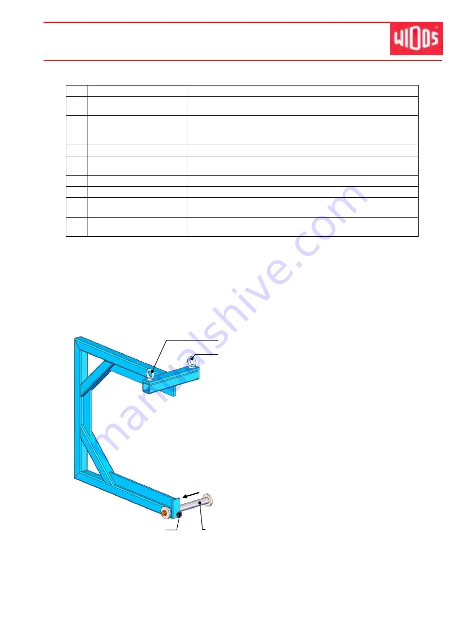
Assembling aid:
The assembling aid is used for all reducer inserts.
Suspend the reducer inserts for the right clamping
rings from the axis (mounted to the left side as
illustrated).
Then lift the assembling aid e.g. by a crane to ring
bolt 1 hinging the reducer insert vertically.
If you want to put the reducer inserts into the left
clamping rings, use ring bolt 2.
Detach the knurled screw and shift the axis in
arrow direction up to limit stop.
Fix the axis again by the knurled screw.
Ring bolt 1 for right clamping rings
Axis in position for right clamping rings
Knurled screw
Ring bolt 2 for left clamping rings


