background image

All information, illustrations and specifications in these operating instructions are based on the latest information available at the time of 

publication. We reserve the right to make design changes at any time without prior notification


33

6.0. Maintenance 

6.6. Adjust seed rail 


CAUTION:


The tension springs are 
tensioned.  
- RISK OF INJURY ! 


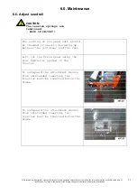
The setting of the seed rail should 
be changed if seed is building up 
between the container and the rail. 


Lift out the Terra Seed using the 
rear hydraulic system of the 
tractor. 


To safeguard the attachment device 
from unintended lowering, two 
trestles must be inserted below the 
frame. 


To safeguard the attachment device 
from unintended lowering, two 
trestles must be inserted below the 
frame. 


Summary of Contents for 497.001

Page 1: ...Translation of original Operating Instructions TERRA SEED 497 001 From equipment I D No Status January 2010 497 99 01 ...

Page 2: ...lustrations and specifications in these operating instructions are based on the latest information available at the time of publication We reserve the right to make design changes at any time without prior notification 2 ...

Page 3: ...lustrations and specifications in these operating instructions are based on the latest information available at the time of publication We reserve the right to make design changes at any time without prior notification 3 ...

Page 4: ...lowing The maintenance requirement for synthetic turf fields differs depending on the layout and the used synthetic turf We recommend that you consult with your groundsman or synthetic turf manufacturer to clarify the suitability of maintenance machines before usage BEFORE DELIVERY OF THIS MACHINE your dealer performed a pre delivery inspection to ensure optimal performance DIE TERRA SEED IS DESIG...

Page 5: ...eight adjustment 18 4 3 Adjusting for Transport 18 4 4 Attaching the support wheels optional 19 4 5 Adjustment with support wheels optional 20 4 6 Prepare the Terra Seed for a trial run 21 23 4 7 Trial run 24 4 8 Sowing table 25 5 0 Operation 26 27 5 1 General 26 5 2 Correct sequence for engaging 27 5 3 Working with the Terra Seed 27 6 0 Maintenance 28 37 6 1 General 28 6 2 Cleaning the TERRA SEED...

Page 6: ...ty instructions contained in these operating instructions as well as all those attached to the machine The warning signs must be kept in good condition i e readable Replace missing or damaged warning signs Ensure that new equipment and spare parts are provided with the appropriate safety signs Replacement warning signs are available from your dealer Familiarise yourself with the operation of the m...

Page 7: ...sult in impairment or loss of hearing Wear a suitable hearing protective device such as earmuffs or earplugs A safe operation of the machine requires the full attention of the operator Do not wear radio or music headphones while operating the machine STAY CLEAR OF ROTATING DRIVE SHAFTS Carelessness in the area of the rotating drive shafts can result in serious injury or even death Always ensure th...

Page 8: ...g parts EXERCISE CAUTION IN THE CASE OF LINE LEAKAGE Leaking high pressure fluids can penetrate the skin and cause serious injury For this reason depressurise the system before disconnecting lines Ensure that all line connections are leak proof before the pressure builds up again in the system It is difficult to see hydraulic oil leaking from a small opening For this reason use a piece of cardboar...

Page 9: ...ng turns Ensure safe traffic conditions by using hand signals or indicators Use headlights hazard warning lights indicators and other safety equipment i a w the respective legal provisions Keep safety equipment in good working order Replace missing or damaged parts A set of safety lights is available from your dealer AVOID HEAT DEVELOPMENT NEAR PRESSURISED FLUID LINES A highly flammable mist can f...

Page 10: ...c fumes and dust Hazardous fumes can be generated when paint is heated due to welding soldering or using a welding torch All work is to be performed outdoors or in a well ventilated area Dispose of paints and solvents i a w the appropriate regulations Remove paint before welding or heating parts The dust generated due to the sandblasting or grinding of parts must not be inhaled For this reason wea...

Page 11: ...tached to the machine at several important positions The hazard is identified via a warning triangle A second symbol informs you how the injury can be prevented by acting appropriately These warning signs their placement on the machine and a brief explanation are given below Operating instructions These operating instructions contain all important information necessary for the safe operation of th...

Page 12: ...iliar with all equipment and operating elements as well as their function before operating the machine Make sure that all protective devices have been properly mounted It will be too late for this during operation In the working area the user is responsible for the safety of other persons The corresponding regulations must be observed on public roads Before starting check the close up range childr...

Page 13: ...ractor and machine match each other When the machine is in transport position always ensure that the side locking of the tractor three point linkage is sufficiently secure Observe the max permissible axle load of the tractor There a risk of injury through crushing or shearing in the area of the machine parts which can be raised The warning and information signs on the machine contain important inf...

Page 14: ... with cat 1 Mount the lower guide bolt on the outside in the lowest possible location bore You thus achieve a maximum lift travel 1 Mount lower guide to bolt A and secure with linch pin 2 Slightly lift bottom handlebar to relieve supports 3 Peg supports in the third bore from the bottom and secure 4 Carefully lower bottom handlebar 5 Peg upper handlebar with bolts B on the three point frame in the...

Page 15: ...ith cat 0 Mount the lower guide bar bolt on the inside in the lowest possible location bore You thus achieve a maximum lift travel 1 Mount lower guide to bolt A and secure with linch pin 2 Slightly lift bottom handlebar to relieve supports 3 Peg supports in the third bore from the bottom and secure 4 Carefully lower bottom handlebar 5 Peg upper handlebar with bolts B on the three point frame in th...

Page 16: ...sconnected when the engine is shut off and the PTO shaft drive is switched off Secure the attachment device against rolling away 3 2 Dismantle the Terra Seed from the tractor Proceed as follows for disconnection 1 Lower Terra Seed to ground 2 Release upper guide bar A and disconnect from three point frame 3 Lightly lift bottom handlebar 4 Peg supports in the second bore from the top and secure 5 L...

Page 17: ...d without safety devices In doing so you expose yourself and others to extreme danger When moving off ensure that the immediate area of the machine is clear e g no children nearby Take particular care when working on a slope DANGER OF TILTING The warning and information signs attached to the machine contain important information to ensure safe operation Observe these instructions for your own safe...

Page 18: ... Operation 4 2 Adjust the rough comb Adjustments can be made on the upper guide bar of the tractor Lift out the Terra Seed slightly Adjust upper guide bar Lower the Terra Seed Setting the upper guide bar A to short increases the pressure of the rough comb on the ground Setting the upper guide bar to A long reduces the pressure of the rough comb on the ground 4 3 Adjusting for Transport The control...

Page 19: ...available at the time of publication We reserve the right to make design changes at any time without prior notification 19 4 0 Before Initial Operation 4 4 Attaching the support wheels optional Insert bolt into bore and secure with clamp sleeve Push support wheel onto bolt Fasten with washer lock washer and SKT screw ...

Page 20: ... 4 5 Adjustment with support wheels optional Always carry out adjustments on a flat paved surface Lift Terra Seed into the desired position using the tractor s rear hydraulic system Lower support wheels onto the ground Secure setting by tightening the fastening screw Insert upper guide with bolt into slotted hole on three point frame and secure with linch pin Adjust the upper guide so that the bol...

Page 21: ...4 0 Before Initial Operation 4 6 Prepare the Terra Seed for a trial run The trial run is used to determine the correct slider position for sowing the required amount of seed The slider must be closed for filling the adjusting lever must be in neutral position for this Open lid Fill up with seed until the brush roller is covered Lift out the Terra Seed for the purpose of adjusting Remove the collec...

Page 22: ... latest information available at the time of publication We reserve the right to make design changes at any time without prior notification 22 4 0 Before Initial Operation 4 6 Prepare the Terra Seed for a trial run Insert collection pan Attach collection pan d Release crank lever and remove crank e ...

Page 23: ... check that the amount of a particular seed is correct adjust the adjusting lever in accordance with the sowing table see Chapter 4 6 The specifications in the sowing table see Chapter 4 6 only serve as a guideline Lift the brush strip g Lifting the brush strip will open the automatic catch of the seed box With the brush strip lifted rotate the shaft with the crank for the number of revolutions sp...

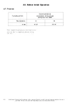
Page 24: ... the time of publication We reserve the right to make design changes at any time without prior notification 24 4 0 Before Initial Operation 4 7 Trial run Terra Seed 160 Crank revolutions revolutions of the wheel with tyres 11x7 4AM Revolutions 8 16 Area 10 m 20 m The specified wheel revolutions allow for a medium wheel slip of 5 ...

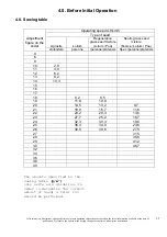
Page 25: ...seed mixture Lolium Poa Sports grass seed mixture Festca Lolium Poa Adjustment figure on the slider stolonifera perenne perenne pratensis Spec perenne pratensis 4 6 8 10 2 0 11 4 0 12 6 2 13 8 2 14 10 3 15 16 17 18 9 2 8 5 19 11 8 10 8 20 14 5 13 2 9 7 21 18 8 16 7 11 6 22 23 2 20 3 13 6 23 27 7 25 2 16 7 24 32 3 30 3 19 8 25 36 4 34 9 23 6 26 40 5 39 6 27 5 27 31 5 28 35 6 29 41 2 30 46 7 32 34 3...

Page 26: ...ible for the safety of third parties in the working area Beware of foreign bodies when working Do not reverse when the TERRA SSEED is operating Avoid big changes in direction while using articulated tractors Drive only with the protective guard lowered The rear hydraulics of the tractor must always be in floating position for operation Ensure that the protective guard is secured on both sides with...

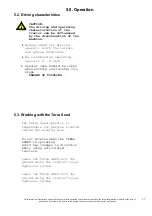
Page 27: ...machine Always adapt the driving speed to match the terrain and ground conditions We recommend an operating speed of 4 8 km h Special care should be taken when working and turning on a slope DANGER OF TOPPLING 5 3 Working with the Terra Seed The Terra Seed operator is responsible for persons located inside the working area Do not reverse when the TERRA SSEED is operating Avoid big changes in direc...

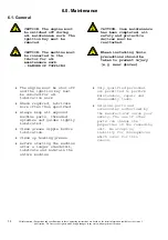
Page 28: ...stalling tools precautions should be taken to prevent injury e g wear gloves The engine must be shut off and the ignition key must be removed for all lubrication work Where required lubricate more often than specified Always keep all exposed machine parts threaded spindles and guides lightly lubricated Clean grease nipple before lubrication Clean up leaking grease Before starting the machine after...

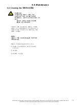
Page 29: ...ithout prior notification 29 6 0 Maintenance 6 2 Cleaning the TERRA SEED CAUTION Cleaning must only be carried out using hand brushes suction devices or air never with bare hands RISK OF INJURY Clean the machine daily when work is completed to ensure a faultless function during the next usage NOTE empty the seed hopper before cleaning Main cleaning points are Seed container with brush roller Slide...

Page 30: ...ck attachment settings see Chapter 2 0 Remove any seed that is caught Slider cannot be opened Remove clean and assemble the tension springs of the seed bar Dirt in the grooves of the V belt pulleys Clean the groove of the V belt pulleys No or insufficient sowing of seed V belt has jumped the groove Apply V belt and tension V belt see chapter 6 4 Move lever into O position or lift device Remove any...

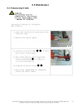
Page 31: ...tensioning V belts CAUTION The machine must be connected to the tractor for all maintenance work DANGER OF TOPPLING Proceed as follows to retension the V belts 1 Shut off the tractor and remove the ignition key 2 Remove the drive guard 3 Loosen screw fittings c e of both pillow block bearings 4 Move both pillow block bearings evenly backwards d to ensure a clean forward drive 5 Tighten screw fitti...

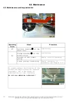
Page 32: ...e 6 5 Maintenance and inspection list Operating hours Check Procedure 20 Vertical bearingc of the wheel axle Lubricating Flange bearing d of the brush roller Lubricating Grooves of the V belt pulley Check clean if necessary 50 V belt pulley tensioning Check retension if necessary see Chapter 6 4 To ensure proper functioning of the slider the bearing must be checked regularly Put a few drops of lub...

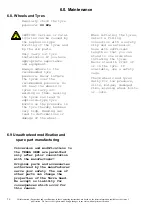
Page 33: ...Adjust seed rail CAUTION The tension springs are tensioned RISK OF INJURY The setting of the seed rail should be changed if seed is building up between the container and the rail Lift out the Terra Seed using the rear hydraulic system of the tractor To safeguard the attachment device from unintended lowering two trestles must be inserted below the frame To safeguard the attachment device from unin...

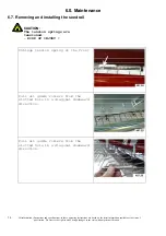
Page 34: ...ht to make design changes at any time without prior notification 34 6 0 Maintenance 6 7 Removing and installing the seed rail CAUTION The tension springs are tensioned RISK OF INJURY Unhinge tension spring at the front Pull all guide rollers from the slotted hole in a diagonal downward direction Pull all guide rollers from the slotted hole in a diagonal downward direction ...

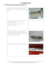
Page 35: ...without prior notification 35 6 0 Maintenance 6 7 Removing and installing the seed rail When inserting the seed rail the bolt must be inserted in the slotted hole Attach loose guide rollers to tension springs Attach loose guide rollers to tension springs When hinging the guide rollers always ensure that the shim rings rest against the inside of the guide rollers on both sides Hinge tension spring ...

Page 36: ... tyres can lead to explosion type tyre bursts as the pressure in the tyre thereby becomes very high Welding can lead to deformations or damage of the wheel When inflating the tyres select a filling connection with a safety clip and an extension hose with sufficient length so that you can stand to one side when inflating the tyres Never stand in front of or on the tyre If available use a safety cag...

Page 37: ...isassembling the machine Read the Section Safety and Precautions and observe local safety regulations The dangers are as follows Heavy parts which could fall down after disassembly Sharp edges The parts might topple over and crush someone Disassembly for Disposal 1 Place the equipment on firm ground 2 Disassemble the machine working from top to bottom IMPORTANT Strictly observe the regulations and...

Page 38: ...blication We reserve the right to make design changes at any time without prior notification 38 7 0 Equipment 7 1 Scope of Delivery Terra Seed with coarse finger tine harrow chassis and brush rail Three point linkage frame for CAT I and CAT 0 Operating instructions transfer declaration with guarantee card 7 2 Special Equipment Support wheel kit ...

Page 39: ...e length from lower guide bar connection 780 mm B Machine width 1800 mm Machine width with support wheel kit 2200 mm C Machiune height in parking position 925 mm D Working width 1550 mm E Height up to lower guide bar connection bottom 235 mm Min power required for tractor 15 KW 20 PS Operating speed 4 8 km h Tyre equipment at back 11x7 4AM 4PR Diameter of tires 260 mm Tyre pressure 0 6 bar Weight ...

Page 40: ...5 675 1150 850 1075 800 1350 1000 M27 490 360 625 450 950 700 1200 875 1350 1000 1700 1250 1600 1150 2000 1500 M30 675 490 850 625 1300 950 1650 1200 1850 1350 2300 1700 2150 1600 2700 2000 M33 900 675 1150 850 1750 1300 2200 1650 2500 1850 3150 2350 2900 2150 3700 2750 M36 1150 850 1450 1075 2250 1650 2850 2100 3200 2350 4050 3000 3750 2750 4750 3500 DO NOT use these values if a different torque ...

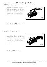
Page 41: ...3 Chassis Number Enter the respective product identification no in the space provided below Always quote this number when ordering spare parts or in case of warranty claims Veh Id no 497 _ _ _ _ _ _ 9 4 ID number for seed box Enter the respective product identification no in the space provided below Always quote this number when ordering spare parts or in case of warranty claims Id Nr SAAT_ _ _ _ ...

Reviews: