All information, illustrations and specifications in this manual are based on the latest information
available at the time of publication. We reserve the right to make changes at any time without notice.
16
2.0. Assembly
2.1. General
Attention:
The machine must be attached
to the tractor for all work.
Lift the attached machine
with the rear hydraulics
until the stand can be
inserted into one of the top
holes.
- RISK OF INJURY!
For this work, please use your
personal protective equipment
(PSA) such as: gloves,
goggles, ear protectors.
2.2. Mounting support wheels
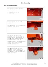
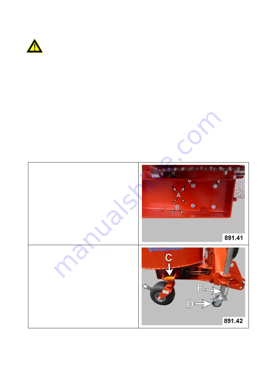
The mounting points for the two
support wheel holders are:
4 threaded holes (A)
2 holes (B)
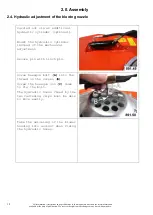
Figure 891.42 shows the right
support wheel (C) mounted and
the locked wheel is rotated to
the back.
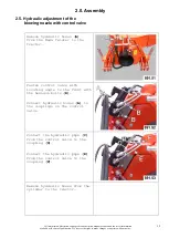
The included support roller with
brake (D) must be fastened to
the bottom of the stand (E).


