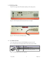
The low voltage DC output at the rear side of the power supply is provided by 4 mm sockets
(Figure 2.3: PL512 Rear Side). The channels are arranged from left to right starting with U0.
Positive output is up and negative output is down.
The sense lines are routed to three DSUB connectors (four channels each).
DSUB9 male
Pin
Left Connector (U0..U3)
Middle Connector (U4..U7)
Right Connector (U8..U11)
1
U0 Sense +
U4 Sense +
U8 Sense +
6
U0 Sense -
U4 Sense -
U8 Sense -
2
U1 Sense +
U5 Sense +
U9 Sense +
7
U1 Sense -
U5 Sense -
U9 Sense -
3
U2 Sense +
U6 Sense +
U10 Sense +
8
U2 Sense -
U6 Sense -
U10 Sense -
4
U3 Sense +
U7 Sense +
U11 Sense +
9
U3 Sense -
U7 Sense -
U11 Sense -
5
not connected
not connected
not connected
Table 7: Sense Connector Pin Assignment
3 PL512 Control and Setup via USB
The PL512 can be controlled with the MUSEcontrol software. Without the
Display
option
this is the only way to change the network (TCP/IP) settings.
The USB interface is primarily intended to be used to configure the
power supply. The Ethernet connection is designated for remote control
and monitoring.
Requirements
●
X86-Computer with USB connection (USB2 recommended)
●
Microsoft Windows XP
Features
●
Setup of the TCP/IP network parameters
●
Global overview of all power supply channels
●
Detailed configuration of the power supply channels
●
Save and reload of configuration data
3.1 Installation
The installation software (MUSEcontrol-x.x.x.x.msi) is free available at the download area
of our website (
www.wiener-d.com
→ Support → Downloads).
Please install the software before connecting the power supply to the
USB. The necessary USB-driver is included in the installation.
8. June 2010
10
*00679.A1


