9
2.
Technical data
2.1
General technical data
1
With plastic bearing/roller bearings (z-type).
2
The back-tilt moment has been calculated at 18 Mpa (180 bar) working pressure.
3
Two positions from inside fork to centre of rotating shaft.
4
Continuously adjustable from inside fork to centre of rotating shaft.
Model
Letter Description
K54A/K54C/SK54A/SK54C
L
Rotating to the left
R
Rotating to the right
Z
Industrial model with adjustable tapered roller bearings
K54A/K54C
I
Plug-in third fork
O
Foldaway third fork
SK54A/SK54C
E
Electrically controlled reversing valve
S
4-hose connection
Table 2.1.2- Description data on model plate
Model
K54A-I
K54A-(Z)-O
K54C-I
K54C-(Z)-O
Max. carrying capacity
2500 kg
2500 kg
3500 kg
3500 kg
Weight
1
240 kg
270/285 kg
315 kg
345/360kg
Max. working pressure
22Mpa (220 bar)
22Mpa (220 bar)
22Mpa (220 bar)
22Mpa (220 bar)
Back-tilt moment
2
6,84 KNm
6,84 KNm
6,84 KNm
6,84 KNm
Center of gravity
133 mm
158 mm
134 mm
158 mm
Frontal extension length 165 mm
185 mm
185 mm
Height of the fork carrier 407 mm (FEM II)
407 mm (FEM II)
508 mm (FEM III)
508 mm (FEM III)
Rotation angle
180°
180°
180°
180°
Fork carrier width
1000 mm
1000 mm
1200 mm
1200 mm
Side-shift
Nee
Nee
Nee
Nee
Third fork plug-in
3
675 of 775 mm
-
775 of 875 mm
-
Third fork foldaway
4
-
580 – 800 mm
-
680 – 900 mm
Model
SK54A-(Z)-O
SK54C-(Z)-O
Max. carrying capacity
2500 kg
3500 kg
Weight
1
335/350 kg
405/420 kg
Max. working pressure
22Mpa (220 bar)
22Mpa (220 bar)
Back-tilt moment
2
6,84 KNm
6,84 KNm
Center of gravity
141 mm
145 mm
Frontal extension length 173 mm
188 mm
Height of the fork carrier 407 mm (FEM II)
508 mm (FEM III)
Rotation angle
180°
180°
Fork carrier width
1000 mm
1200 mm
Side-shift
Ja, 200mm
Ja, 200mm
Third fork plug-in
3
-
-
Third fork foldaway
4
580 – 800 mm
680 – 900 mm
Table 2.1.1- Various models of the WIFO box rotator
Summary of Contents for K54A-I
Page 2: ......
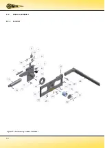
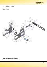
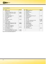
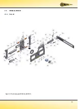
Page 12: ...10 2 2 K54A I and K54C I 2 2 1 Parts list Figure 2 2 1 Parts drawing for K54A I and K54C I...
Page 15: ...13 2 3 K54A O and K54C O 2 3 1 Parts list Figure 2 3 1 Parts drawing for K54A O and K54C O...
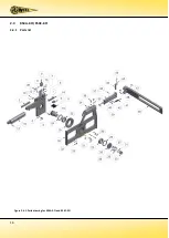
Page 18: ...16 2 4 K54A Z O K54C Z O 2 4 1 Parts list Figure 2 4 1 Parts drawing for K54A Z O and K54C Z O...
Page 21: ...19 2 5 SK54A O SK54C O 2 5 1 Parts list Figure 2 5 1 Parts drawing for SK54A O and SK54C O...
Page 29: ......
Page 30: ......
Page 31: ......


