18
1.
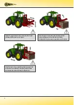
If the box is raised at all, the upper clamp should be horizontal or sloping on the box in the direction of the
valve front plate. This can be adjusted as follows:
Adjusting the upper clamp
-
Remove the pins and securing clips from the upper clamp and the pin and securing clip from the
clamping cylinder.
-
Using the box and the pins with their securing clips, adjust the height of the upper clamp.
-
Set the upper clamp vertically, slide the clamping cylinder(s) fully home and secure to the tipping
frame using the pin. With the clamping cylinder in its extended position, the upper clamp will now
pass around 10° through the 90° position. This is sufficient to clamp the box.
2.
With the back of the box against the tipping frame, the front plate of the upper clamp should be just on the
edge of the box, against the front of the box. This can be adjusted as follows:
-
Loosen the upper clamp securing bolts.
-
Slide the valve up against the box and retighten the upper clamp using the securing bolts and
locknuts (105Nm).
-
The slide out tubes should be adjusted so that they fit just within the width of the box.
The WIFO forward tipping box rotator is now ready for use.
Ensure that the hydraulic hoses and electrical cables can not become trapped during use.

