10
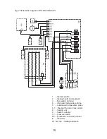
Fig. 7 Schematic diagram of POW-LCD MULTI
1 – thermal switch
2 – display board and keyboard
3 – flow switch (turbine)
4 – inlet water temperature probe
5 – outlet water temperature probe
6, 7 – flow switch and air lock sensor
8 – heating unit
9 – heater controller
10 – pressure switch
PE – protective conductor terminal
E – electrode
G1, G2, G3 – heating elements


