Operating Instructions Temperature Indicating Controller CS4H / CS4L
V1.1
•
05/2006
- 14 -
Caution
• The terminal blocks of the CS4H and CS4L are designed to be wired from the left side.
The lead wire must be inserted from the left side of the terminal, and fastened with the terminal screw.
• Dotted lines show options. If the option is not designated, there are no terminals.
• When A2 (option) and Heater burnout alarm (option) are applied together, use terminals 12-13 for A2,
and 9-10 for Heater burnout alarm.
• When Heating/Cooling control (option) and Heater burnout Alarm (option) are applied together, use
terminals 9-10 for the Heating/Cooling control and 12-13 for the Heater burnout alarm.
• When A2 (option) and LA (option) are applied, they use common output terminals.
• When Isolated power output (option) is applied, Heating/Cooling control (option) and Heater burnout
Alarm (option) cannot be applied with it.
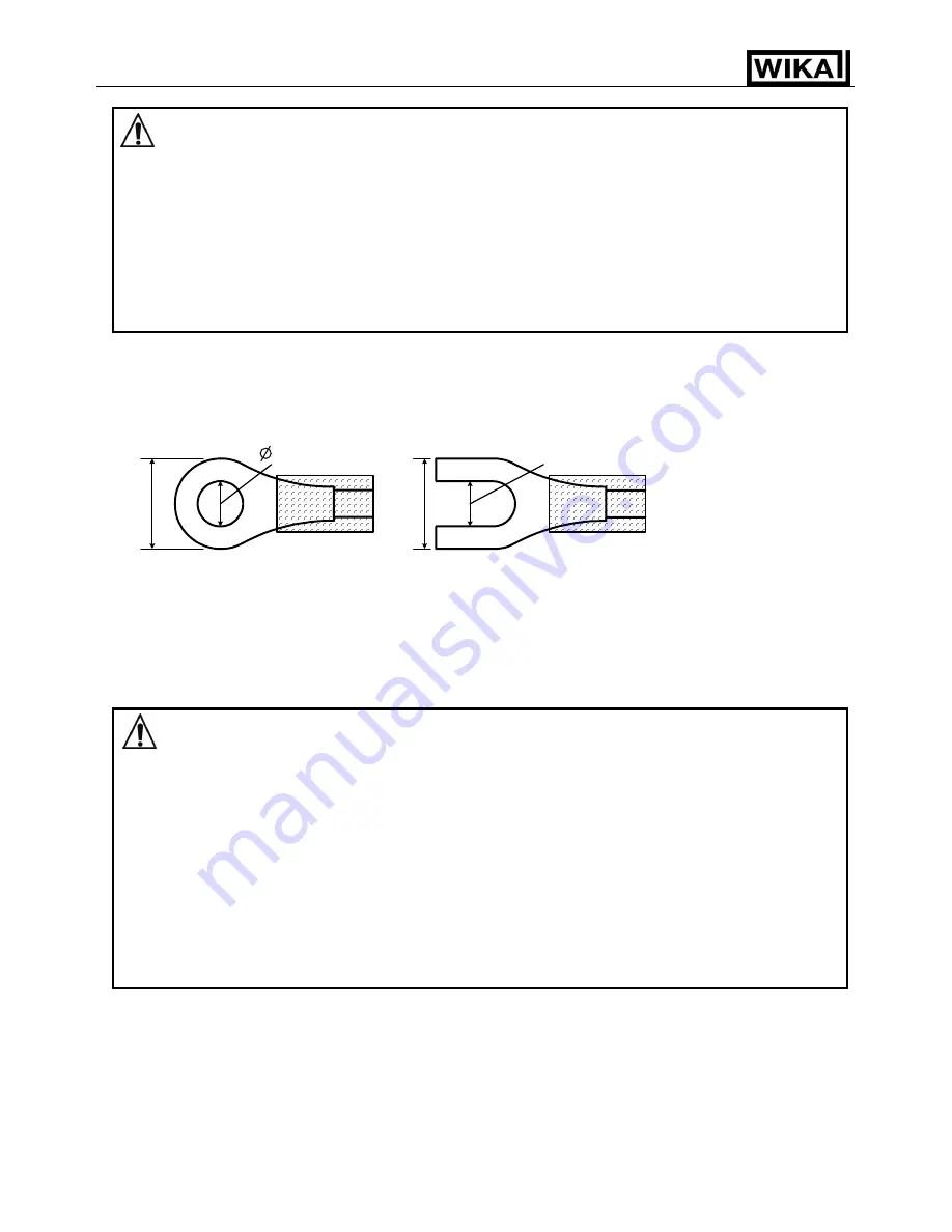
Lead wire solderless
terminal
Use a solderless terminal with isolation sleeve that fits in the M3 screw as shown below.
Designate the torque 0.6 Nm to 1.0 Nm.
(Fig. 4.1-2)
4.2 Wiring connection example
Caution
• Use a thermocouple and compensating lead wire according to the sensor input specifica-
tions of this controller.
•
Use a 3-wire RTD system according to the sensor input specifications of this controller.
•
This controller has no built-in power switch or fuse. It is necessary to install them in the circuit
near the external controller.
(Recommended fuse: Time-lag fuse, rated voltage AC 250V, rated current 2A)
• When using a AC/DC 24V for the power source, do not confuse the polarity when it is DC.
• When using a relay contact output type, use a relay according to the capacity of the load to pro-
tect the built-in relay contact.
• When wiring, keep input wires (thermocouple, RTD, etc.) away from AC sources or load wires to
avoid external interference.
• Use a thick wire
(1.25 … 2.0 mm
2
) for the earth ground.
5
.8mm or
less
3.2mm
3.2mm
5
.8mm or
less


