Operating Instructions Temperature Indicating Controller CS4H / CS4L
V1.1
•
05/2006
- 42 -
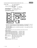
Supply voltage
: 100 ... 240 V AC 50/60Hz or
24 V AC/DC 50/60Hz
Allowable voltage fluctuation range
100 ... 240 V AC : 85 ... 264 V AC
24 V AC/DC
: 20 ... 28V AC/DC
Ambient temperature
: 0 ... 50 °C (32 ... 122 °F)
Ambient humidity
: 35 ... 85 %RH (no condensation)
Power consumption
: Approx. 8 VA or 8 W
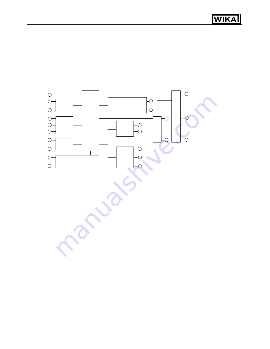
Circuit Isolation configuration
• When OUT1 is Logic level DC 0/12 V or Analogue current signal (4 ... 20 mA) and OUT2 is Logic level
DC 0/12 V or Analogue current signal (4 ... 20 mA), between A to B is non-isolated.
• When OUT1 is Logic level DC 0/12 V or Analogue current signal (4 ... 20 mA), between A to C and A
to D are non-isolated.
When OUT2 is Logic level DC 0/12 V or Analogue current signal (4 ... 20 mA), between B to C and B
to D are non-isolated.
Isolation resistance
10 M
Ω
or greater at 500 V DC for other combinations except the above mentioned
Dielectric strength
Between input terminal and ground terminal, 1.5 kV AC for 1 minute
Between input terminal and power terminal,
1.5 kV AC for 1 minute
Between output terminal and ground terminal, 1.5 kV AC for 1 minute
Between output terminal and power terminal, 1.5 kV AC for 1 minute
Between power terminal and ground terminal, 1.5 kV AC for 1 minute
Mass
: CS4H (approx. 250 g), CS4L, (approx. 370 g)
External dimension
: CS4H, 48 x 96 x 100 mm (W x H x D)
CS4L, 96 x 96 x 100 mm (W x H x D)
Material
: Case, Flame resistant resin
Color
: Case, black
Drip-proof/Dust-proof
: IP66 for the front part
OUT1
A
B
C
Power
source
A2 output, Heater
burnout alarm output
CT input
Input
Ground
Isolation
SV2
OUT2, Heater burnout
alarm output or
Insulated power output
3
1
2
5
4
9
8
7
6
10
20
18
19
17
16
15
14
13
12
A1 output
17
14
11
Communication
D
or Look break alarm
output


