Operating Instructions Temperature Indicating Controller CS4H / CS4L
V1.1
•
05/2006
- 46 -
Heating/Cooling control [option codes: DR2, DS2, DA2]
When the option 2. control output is added, one more option Alarm output 2 or Heater burnout alarm can
be added.
OUT2 proportional band : 0.0 ... 10.0 times OUT1 proportional band (ON/OFF action when set to 0.0)
OUT2 integral time
: The same as that of OUT1
OUT2 derivative time
: The same as that of OUT1
OUT2 proportional cycle : 1 ... 120 seconds
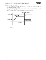
Overlap band/Dead band : For thermocouple and RTD inputs, –100.0 ... 100.0 °C (°F)
For DC current and voltage inputs, –1000 ... 1000
(The placement of the decimal point follows the selection)
OUT2 ON/OFF action hysteresis
For thermocouple and RTD inputs, 0.1 ... 100.0 °C (°F)
For DC current and voltage inputs, 1 ... 1000
(The placement of the decimal point follows the selection)
Output
Relay contact output [DR2]
Control capacity 3 A, 250 V AC (resistive load)
1 A, 250 V AC (inductive load cos ø = 0.4)
Electrical life 100,000 times
Logic level DC 0/12 V [DS2]
12
+ 2
- 0
V DC maximum 40 mA (short circuit protected)
Analogue current signal (4 ... 20 mA) [DA2]
Load resistance, maximum 550
Ω
OUT2 action mode selection function:
One cooling mode can be selected by the key operation from the following.
• Air cooling (Linear characteristic)
• Oil cooling (1.5th power of the linear characteristic)
• Water cooling (2nd power of the linear characteristic)
Serial communication [option code: CR5]
When this option is added, SV1/SV2 external selection function is disabled.
The following operations can be carried out from the external computer.
(1) Reading and setting of SV, PID values and each setting value
(2) Reading of PV and action status
(3) Change of the functions
Communication circuit
: Based on EIA RS-485
Communication method : Half-duplex communication start stop synchronous
Data transfer rate
: 2400, 4800, 9600, 19200 bps (Selectable by key)
Parity
: Even, Odd and None (Selectable by key)
Stop bit
: 1 and 2 (Selectable by key)
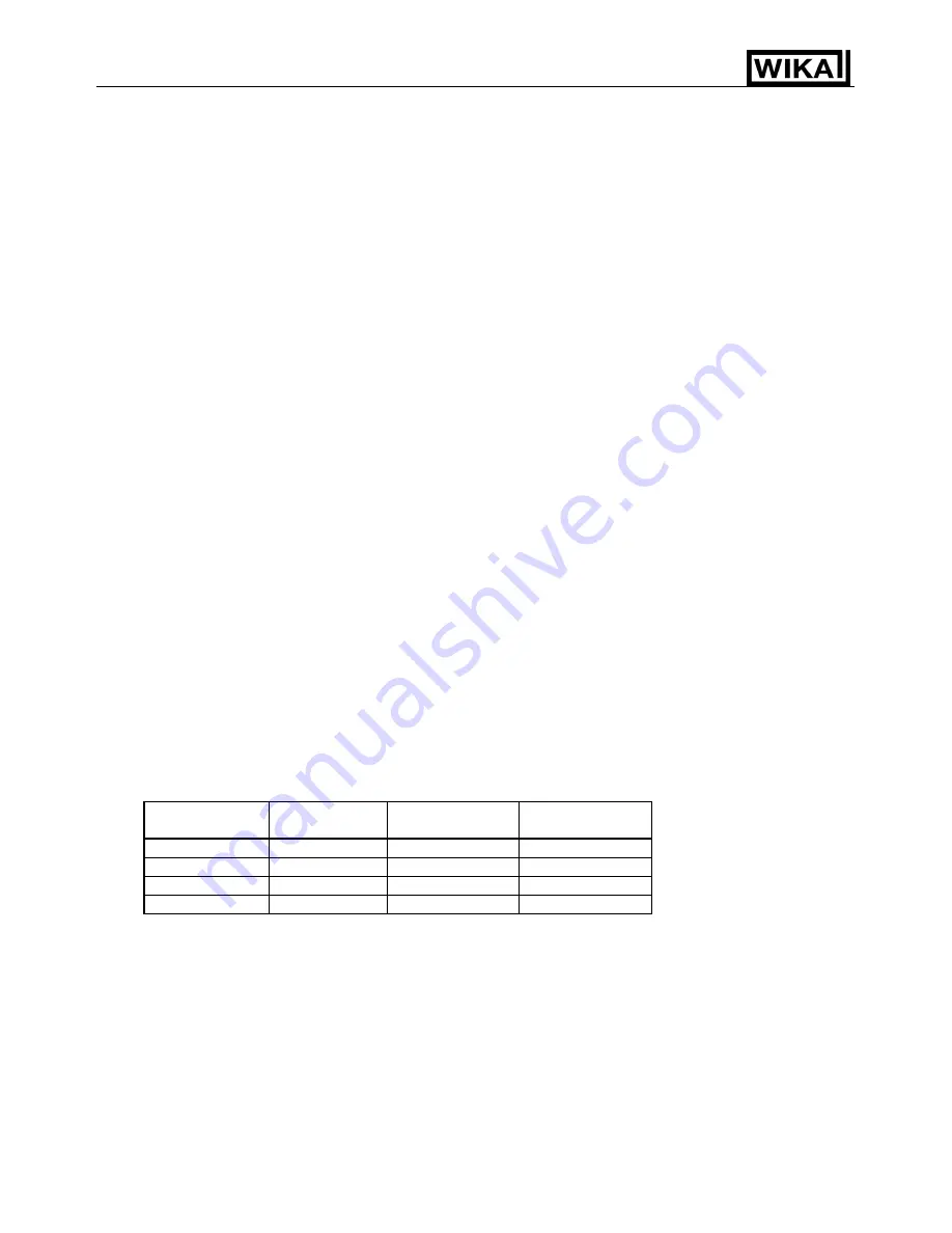
Data format
Communication
protocol
WIKA protocol Modbus ASCII
Modbus RTU
Start bit
1
1
1
Data bit
7
7
8
Parity
Even
Selection (Even) Selection (None)
Stop bit
1
Selection (1)
Selection (1)
Data bit is automatically changed depending on the selection of communication protocol.
Digital external setting
:
Receives digital setting value from WIKA programmable controller (with option SVTC).
(It is necessary to set the Setting value lock function to Lock 3 for the CS4H and CS4L.)
When the data from WIKA programmable controller exceeds SV high limit or SV low limit, the CS4H or
CS4L ignores the value, and performs the control with SV high limit or SV low limit.
Transmitter supply (isolated power output) [option code: P24]
Output voltage
: 24 ±3 V DC (when load current is 30 mA)
Ripple voltage
: Within 200 mV (when load current is 30 mA)
Maximum load current : 30 mA
Terminal cover [option code: KAB]
Electrical shock protecting terminal cover
( ): Basic setting value


