14033590.01 10/2014 GB/D
WIKA operating instructions model CS4S
23
GB
P
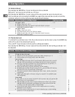
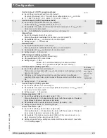
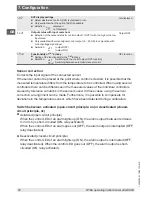
Control Output 1 (OUT1) proportional band
■
Input of the proportional band for control output 1.
By entering the value 0 or 0.0, the controller is configured as an
ON
/
OFF
controller.
■
0 ... 1,000 °C (2,000 °F), 0.0 ... 999.9 °C (°F) or 0.0 ... 100.0 %
10 °C
p_b
Control output 2 (OUT2) proportional band
■
Input of the proportional band for control output 2.
Control mode
ON
/
OFF
with input of the value 0 or 0.0
■
Not available if the option 2 control output [DT2] is not present, or if
ON
/
OFF
control
mode is set on control output 1.
■
0.0 ... 10.0 (Multiplier for proportional band for control output 1)
1.0
1
Integral time
■
Input of the integral time for the control.
Entering the value 0 deactivates this function (⇒ control mode PD).
■
Not available with
ON
/
OFF
control mode for control output 1
■
Setting range: 0 ... 1,000 seconds
200 s
d
Derivative time
■
Input of the derivative time for the control.
Entering the value 0 deactivates this function (⇒ control mode PI).
■
Not available with
ON
/
OFF
control mode for control output 1
■
Setting range: 0 ... 300 seconds
50 s
A
ARW (Anti-reset windup) parameter
■
Input of the paramter for the anti-reset-windup
■
Only available with PID control mode
■
Setting range: 0 ... 100 %
(Values > 50 %: additional damping to reduce overshoot
Values < 50 %: generate a steeper rise with "Start up")
50 %
c
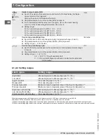
Control output 1 (OUT1) cycle time
■
Input of the cycle time for control output 1
This function is not available with
ON
/
OFF
control mode nor with analogue current
signal control output.
■
With relay control output, shortening the cycle time leads to more-frequent
switching of the output relay, which increases the wear and shortens the service
life.
■
Setting range: 1 ... 120 seconds
30 s (relay
control output)
or 3 s (logic
level control
output)
Logikpegel)
c_B
Control output 2 (OUT2) cycle time
■
Input of the cycle time for control output 2
■
Not available if the option 2, control output [DT2] is not present, or if
ON
/
OFF
control
mode is set on control output 2.
■
Setting range: 1 ... 120 seconds
3 s
A1
Alarm value alarm 1 (A1)
■
Input of the switching value for alarm output 1 (A1).
Entering the value 0 or 0.0 deactivates the alarm (with the exception of the alarm
types process high alarm and process low alarm)
■
Not available when no alarm is selected for alarm type alarm 1 (A1).
■
Setting range: see table “A1, A2 setting ranges”
0 °C
A2
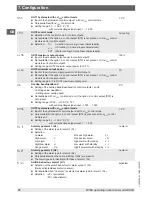
Alarm value alarm 2 (A2)
■
Input of the switching value for alarm output 2 (A2).
Entering the value 0 or 0.0 deactivates the alarm (with the exception of the alarm
types process high alarm and process low alarm)
■
Not available if the options alarm output 2 [2AS] or [2AL] are not present, or no
alarm is selected for the alarm type alarm 2 (A2).
■
Setting range and factory setting are identical with those from alarm 1 (see table
“A1, A2 setting ranges”).
0 °C
7. Configuration


