14033590.01 10/2014 GB/D
WIKA operating instructions model CS4S
27
GB
K
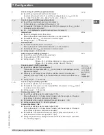
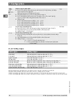
-200 ... +1,370 °C:
-199.9 ... +400.0 °C:
E
E
C
.
C
J
-200 ... +1,000 °C:
J
C
R
0 ... +1,760 °C:
r
C
S
0 ... +1,760 °C:
h
C
B
0 ... +1,820 °C:
b
C
E
-200 ... +800 °C:
E
C
T
-199.9 ... +400.0 °C:
F
.
C
N
-200 ... +1,300 °C:
n
C
PL-II
0 ... +1,390 °C:
PL2 C
C (W/Re5-26)
0 ... +2,315 °C:
c
C
Pt100
-199.9 ... +850.0 °C:
Pf
.
C
JPt100
-199.9 ... +500.0 °C:
JPF
.
C
Pt100
-200 ... +850 °C:
PF C
JPt100
-200 ... +500 °C:
JPF C
4 ... 20 mA
-1,999 ... +9,999:
420A
0 ... 20 mA
-1,999 ... +9,999:
020A
0 ... 1 V
-1,999 ... +9,999:
0 18
0 ... 5 V
-1,999 ... +9,999:
0 58
1 ... 5 V
-1,999 ... +9,999:
1 58
0 ... 10 V
-1,999 ... +9,999:
0 108
K
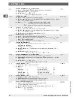
-320 ... +2,500 °C:
-199.9 ... +750.0 °C:
E
E
F
.
F
J
-320 ... +1,800 °C:
J
F
R
0 ... +3,200 °C:
r
F
S
0 ... +3,200 °C:
h
F
B
0 ... +3,300 °C:
b
F
E
-320 ... +1,500 °C:
E
F
T
-199.9 ... +750.0 °C:
F
.
F
N
-320 ... +2,300 °C:
n
F
PL-II
0 ... +2,500 °C:
PL2 F
C (W/Re5-26)
0 ... +4,200 °C:
c
F
Pt100
-199.9 ... +999.9 °C:
Pf
.
F
JPt100
-199.9 ... +900.0 °C:
JPF
.
F
Pt100
-300 ... +1,500 °C:
PF F
JPt100
-300 ... +900 °C:
JPF F
Note:
With the input configuration 4 ... 20 mA or 0 ... 20 mA
there must be a 50 Ω measurement shunt, available
as an option, connected to the terminals 8 and 10.
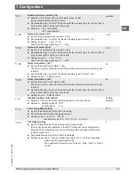
hFLH
End value scaling
■
Scaling the end value
■
Only available with current/voltage signal input
■
Setting range:
scaled start value to maximum value of the input configuration
9,999
hFLL
Start value scaling
■
Scaling the start value
■
Only available with current/voltage signal input
■
Setting range: scaled end value to minimum value of the input configuration
-1,999
dP
Decimal point
■
Setting the decimal point
■
Only available with current/voltage signal input
■
Selection:
no decimal point
0000
1 figure after the decimal point
000
.
0
2 figures after the decimal point
00
.
00
3 figures after the decimal point
0
.
000
no decimal
point
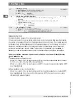
F1LF
Actual value filter time constant
■
Input of the time for the actual value input filter
During the set time, an averaging of the actual value is carried out. If the value is
set too high, this can affect the control result due to the delay.
■
Setting range: 0.0 ... 10.0 seconds
0.0 s
oLH
OUT1 maximum output power
■
Input of the maximum output power for control output 1
■
Not available with
ON
/
OFF
control mode
■
Setting range: OUT1 minimum output power to 100 %
(with relay control output or logic level DC 0/12 V)
OUT1 minimum output power to 105 %
(with control output, 4 ... 20 mA analogue current signal)
100 %
oLL
OUT1 minimum output power
■
Input of the minimum output power for control output 1
■
Not available with
ON
/
OFF
control mode.
■
Setting range: 0 % to OUT1 maximum output power
(with relay control output or logic level DC 0/12 V)
-5 % to OUT1 maximum output power
(control output, 4 ... 20 mA analogue current signal)
0 %
7. Configuration

