background image

14033590.01 10/2014 GB/D

42

WIKA operating instructions model CS4S

GB

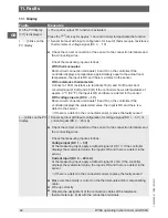
11.1 Display

Faults

Measures

On the PV display

[

OFF

] is displayed

⇒ The control output 

OFF

 function is activated

Press the

 OUT

/

OFF

 key for approx. 1 second in order to deactivate the function

[

----

] blinks on the 

PV display

⇒ Sensor burnout with input configuration for input of thermocouple, resistance 

thermometer or voltage signal (DC 0 ... 1 V).


Check the correct connection of the sensor to the connection terminals and 

the connecting wires.

Check the measuring input as follows:

With thermocouples

Short-circuit connection terminals 18 and 19 on the controller. If the 

controller displays a temperature approximately equal to the actual room 

temperature, the input is OK and there is a defect in the sensor.

With resistance thermometers

Connect a 100 Ω resistance to terminals 18 (A) and 19 (B) and short-

circuit terminals 19 (B) and 20 (B). If the controller shows a temperature of 

approx. 0 °C (32 °F), the input is OK and there is a defect in the sensor.

With voltage inputs (DC 0 ... 1 V)

Short-circuit connection terminals 18 and 19 on the controller. If the 

controller displays the scaled start value, the input is OK and there is a 

defect in the sensor.

⇒ If there is a defect in the connected sensor, replace the 

faulty sensor!

[----] blinks on the PV 

display

⇒ Sensor burnout with input configuration for voltage signal (DC 1 ... 5 V) or 

current signal (DC 4 ... 20 mA)


Check the correct connection of the sensor to the connection terminals and 

the connecting wires.

Check the measuring input as follows:

Voltage input (DC 1 ... 5 V)

At the measuring input, apply a defined signal of DC 1 V. If the controller 

displays the scaled start value, the input is OK and there is a defect in the 

sensor.

Current input (DC 4 ... 20 mA)

At the measuring input, apply a defined signal of 4 mA. If the controller 

displays the scaled start value, the input is OK and there is a defect in the 

sensor.

⇒ If there is a defect in the connected sensor, replace the 

faulty sensor!


Make sure the polarity is correct on the thermocouple and/or compensating 

cable.


Wire up correctly


Observe the assignment of the connection cables of the resistance 

thermometers (A, B, B) with the connection terminals.

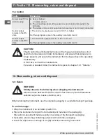
11. Faults

Summary of Contents for CS4S

Page 1: ...GB Operating instructions Betriebsanleitung Temperature controller model CS4S Temperature controller for mounting into control panels Model CS4S Temperaturregler f r den Einbau in Schalttafeln Typ CS4...

Page 2: ...be found at www wika com 2013 WIKA Alexander Wiegand SE Co KG All rights reserved Alle Rechte vorbehalten WIKA is a registered trademark in various countries WIKA ist eine gesch tzte Marke in verschie...

Page 3: ...nsport packaging and storage 13 6 Commissioning operation 14 7 Configuration 18 8 Descriptions of the operating characteristics 32 9 Control mode 38 10 Maintenance and cleaning 41 11 Faults 41 12 Dism...

Page 4: ...le to skilled personnel at any time Skilled personnel must have carefully read and understood the operating instructions prior to beginning any work The manufacturer s liability is void in the case of...

Page 5: ...ntial or commercial installations it can interfere with other equipment under certain conditions In such circumstances the operator is expected to take the appropriate measures Further important safet...

Page 6: ...d on their technical training knowledge of measurement and control technology and on their experience and knowledge of country specific regulations current standards and directives are capable of carr...

Page 7: ...e mains voltage to the output voltage can result in life threatening voltages at the instrument WARNING Do not use this instrument in safety or emergency stop devices Incorrect use of the instrument c...

Page 8: ...rol output 1 3 different versions are possible Relay contact Loading AC 250 V 3 A resistive load AC 250 V 1 A inductive load cos 0 4 Logic level DC 0 12 V max 40 mA short circuit proof for the control...

Page 9: ...red up to max 5 A 10 A 20 A or 50 A the current transformer is included in the delivery Relay contact 3 Loading AC 250 V 3 A resistive load AC 250 V 1 A inductive load cos 0 4 Options and performance...

Page 10: ...as standard The control parameters can be set across broad ranges Auto tuning which facilitates finding the optimal control parameters can be activated The controllers are designed for installation in...

Page 11: ...VT Event display The red LED lights up when the event output is ON Option 2Ax Alarm output 2 and or option W1x heater burnout alarm 9 AT Auto tuning The yellow LED blinks when the auto tuning or the a...

Page 12: ...5 2 8 K L 10 2 3 5 30 30 l k 100 40 12 40 15 30 2 M3 4 3 Dimensions in mm Sealing Screw type mounting bracket 4 3 1 Panel cutout 4 3 2 Current transformer CTL 6S for 5 A 10 A 20 A CTL 12 S36 10L1 for...

Page 13: ...Humidity 35 85 relative humidity without condensation Avoid exposure to the following factors Direct sunlight or proximity to hot objects Mechanical vibration mechanical shock putting it down hard Soo...

Page 14: ...lose to electromagnetic switches or cables carrying high currents Not for direct contact with water oil chemicals or their vapours WARNING Failure to comply with this can destroy the sensor input Thes...

Page 15: ...t rigid enough or a damage is present at the case the compliance with ingress protection IP 66 cannot be guaranteed Control panel thickness for installation 1 15 mm Max installation height 2 000 m Fir...

Page 16: ...tions If an option is not available the corresponding terminal connections will also be missing Use thermocouples and compensating cables in accordance with the input configuration of the controller W...

Page 17: ...power supply ever be connected to the sensor input terminals or the connected sensor be brought into contact with the power supply Solder free cable shoes Use solder free cable shoes with insulated sl...

Page 18: ...ers please follow the procedure in accordance with chapter 7 Configuration Switch on the load circuit The control loop is now in operation and the control system will try to maintain the selected set...

Page 19: ...C 1760 r f 3200 S S C 1760 s f 3200 B b C 1820 b f 3300 E E C 800 e f 1500 T E C 400 0 e F 750 0 N n C 1300 n f 2300 PL II PL2 C 1390 PL2 F 2500 C W Re5 26 c C 2315 c f 4200 Pt100 PE PE C C 850 0 850...

Page 20: ...of the output power Set point level Parameter level Auxiliary parameter level 1 Set point 1 SV1 s Set point 2 SV2 s2 AT auto tuning auto reset ae rSee Control output 1 OUT1 Proportional band p Control...

Page 21: ...ODE MODE MODE MODE MODE MODE MODE MODE MODE MODE MODE Switch behaviour alarm 2 A2 A2LA Hysteresis alarm 1 A1 A1Hy Hysteresis alarm 2 A2 A2Hy Delay time Alarm 1 A1 a1dy Delay time Alarm 2 A2 A2dy Heati...

Page 22: ...uto reset Activation of AT auto tuning AF or auto reset offset correction rhEF Factory setting auto tuning and auto reset deactivated auto tuning After activating auto tuning the AT control indicator...

Page 23: ...teeper rise with Start up 50 c Control output 1 OUT1 cycle time Input of the cycle time for control output 1 This function is not available with ON OFF control mode nor with analogue current signal co...

Page 24: ...hen one of the options 2AR or 2AL is present Setting range 0 150 C F 0 0 150 0 C F with decimal point 0 1 500 current voltage signal inputs decimal point appropriate to the scaling 0 C A1 A2 Setting r...

Page 25: ...e reinstated This mode is used when values are only to be changed temporarily This mode should be set during operation of the controller via the serial interface hH Maximum set point Input of the uppe...

Page 26: ...protocol Selection 1 2 1 7 5 Auxiliary parameter level 2 To activate auxiliary parameter level 2 from the actual value set point screen press the MODE key for approx 3 seconds while at the same time p...

Page 27: ...hFLL Start value scaling Scaling the start value Only available with current voltage signal input Setting range scaled end value to minimum value of the input configuration 1 999 dP Decimal point Sett...

Page 28: ...to OUT2 maximum output power 0 db Overlap band deadband Setting of the overlap band deadband for control outputs 1 and 2 Setting value deadband Setting value overlap band Not available with ON OFF con...

Page 29: ...ected as alarm type for alarm 1 A1 Setting range 0 9999 seconds 0 s A2dY Delay time alarm 2 A2 Input of the delay time for alarm 2 A2 The alarm output is not switched until the set time after the alar...

Page 30: ...trol is desired it is possible that the measured temperature differs from the temperature to be controlled When using several controllers there can be differences in the measured values of the individ...

Page 31: ...changes in the manipulated variable are prevented If the functionality of automatic manual control were to be selected the OFF Function switching control off would not be possible 7 7 Switching contr...

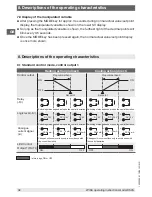
Page 32: ...put 1 Heating action indirect Cooling action direct Control output Proportional band Proportional band Set point Set point Relay R Switching status dependent upon the control deviation Switching statu...

Page 33: ...l S Analogue current signal A LED Control Output 1 OUT1 in this range ON or OFF 8 3 SV1 SV2 external selection SV1 SV2 SV1 SV2 external selection LED display A combination of the external set point se...

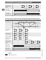
Page 34: ...arm Alarm behaviour Hysteresis Hysteresis Alarm value Set point Alarm value Alarm value Set point Alarm value Alarm output Process high alarm Process low alarm Alarm behaviour Hysteresis Hysteresis Al...

Page 35: ...utput LED display EVT 8 6 Control output 2 three point control heating cooling Control output P band heating P band cooling Set point Control output 1 relay R Switching status dependent upon the contr...

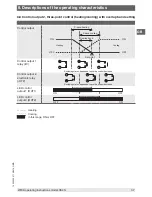
Page 36: ...dependent upon the control deviation Control output 1 logic level S Switching status dependent upon the control deviation Control output 1 analogue current signal A Changes will occur continuously in...

Page 37: ...Overlap band Set point Control output 1 relay R Switching status dependent upon the control deviation Control output 2 electronic relay DT2 Switching status dependent upon the control deviation LED c...

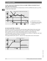
Page 38: ...n the range of the set point and a constant actual value has been maintained one gets the most suitable value by gradually narrowing the proportional band under constant observation of the control res...

Page 39: ...g 20 C is lower than the set point Determining the PID parameters Parameter determination completed Controlling with the control parameters determined through auto tuning AT BIAS value Temperature 20...

Page 40: ...the set point Time Temperature Set point AT starting time 9 3 Auto reset Offset correction PD control can produce a permanent control deviation offset between the actual value and the set point The a...

Page 41: ...he environment from exposure to residual media For information on returning the instrument see chapter 12 1 Return 11 Faults If malfunctions occur please first check the power supply and wiring and th...

Page 42: ...sensor With voltage inputs DC 0 1 V Short circuit connection terminals 18 and 19 on the controller If the controller displays the scaled start value the input is OK and there is a defect in the sensor...

Page 43: ...en is either not normal or instable Select the correct input configuration sensor type and temperature units C or F Input a suitable value for the sensor correction Check the specification of the sens...

Page 44: ...that signal are no longer present and secure the instrument from being put back into operation inadvertently In this case contact the manufacturer If a return is needed follow the instructions given...

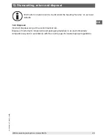
Page 45: ...er the heading Service on our local website 12 2 Disposal Incorrect disposal can put the environment at risk Dispose of instrument components and packaging materials in an environmentally compatible w...

Page 46: ...14033590 01 10 2014 GB D 46 WIKA operating instructions model CS4S GB Appendix EC declaration of conformity...

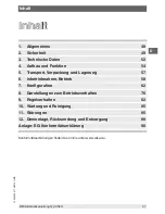
Page 47: ...7 6 Inbetriebnahme Betrieb 58 7 Konfiguration 62 8 Darstellungen zum Betriebsverhalten 76 9 Regelverhalten 82 10 Wartung und Reinigung 85 11 St rungen 85 12 Demontage R cksendung und Entsorgung 88 Anl...

Page 48: ...it zug nglich aufbewahrt werden Das Fachpersonal muss die Betriebsanleitung vor Beginn aller Arbeiten sorgf ltig durch gelesen und verstanden haben Die Haftung des Herstellers erlischt bei Sch den dur...

Page 49: ...n oder Gewerbebereich kann sie unter Umst nden andere Einrichtun gen st rend beeinflussen In diesem Fall kann vom Betreiber verlangt werden angemessene Ma nahmen durchzuf hren Weitere wichtige Sicherh...

Page 50: ...ngstechnik und seiner Erfahrungen sowie Kenntnis der landesspezifischen Vorschriften geltenden Normen und Richtlinien in der Lage die beschriebenen Arbeiten auszuf hren und m gliche Gefahren selbstst...

Page 51: ...usgangsspannung k nnen am Ger t lebensgef hrliche Spannungen auftreten WARNUNG Dieses Ger t nicht in Sicherheits oder in Not Aus Einrichtungen benutzen Fehlerhafte Anwendungen des Ger tes k nnen zu Ve...

Page 52: ...3 verschiedene Ausf hrungen sind m glich Relaiskontakt Belastung AC 250 V 3 A ohmsche Last AC 250 V 1 A induktive Last cos 0 4 Logikpegel DC 0 12 V max 40 mA kurzschlussfest zur Ansteuerung eines elek...

Page 53: ...nal wahlweise ausgelegt bis max 5 A 10 A 20 A oder 50 A der Stromwandler geh rt zum Lieferumfang Relaiskontakt 3 Belastung AC 250 V 3 A ohmsche Last AC 250 V 1 A induktive Last cos 0 4 Optionen und Le...

Page 54: ...ameter sind in weiten Bereichen einstellbar Eine Selbstoptimierung die das Finden der optimalen Regelparameter erleichtert kann aktiviert werden Die Regler sind vorgesehen zum Einbau in eine Schalttaf...

Page 55: ...der Event Ausgang EIN ist Option 2Ax Alarmausgang 2 und oder Option W1x Heizungsdefektalarm 9 AT Auto Tuning Die gelbe LED blinkt wenn die Auto Tuning oder die Auto Reset Funktion aktiv ist 10 TX RX T...

Page 56: ...12 40 15 30 2 M3 56 WIKA Betriebsanleitung Typ CS4S D 4 3 Abmessungen in mm Dichtung Schraubb gel 4 3 1 Schalttafelausschnitt 4 Aufbau und Funktion 4 3 2 Stromwandler CTL 6S f r 5 A 10 A 20 A CTL 12...

Page 57: ...Feuchtigkeit 35 85 relative Feuchte ohne Betauung Folgende Einfl sse vermeiden Direktes Sonnenlicht oder N he zu hei en Gegenst nden Mechanische Vibration mechanischer Schock hartes Aufstellen Ru Damp...

Page 58: ...montiert werden Nicht in direktem Kontakt mit Wasser l oder Chemikalien sowie deren D mpfe WARNUNG Bei Nichtbeachtung kann der Sensoreingang zerst rt werden Diese Regler verf gen weder ber einen einge...

Page 59: ...liegt eine Besch digung am Geh use vor kann die Einhaltung der Schutzart IP 66 nicht garantiert werden Schalttafeldicke f r den Einbau 1 15 mm Max Einbauh he 2 000 m Zuerst den Regler von vorne in die...

Page 60: ...uben befestigen Gestrichelte Linien zeigen Optionen Wenn eine Option nicht vorhanden ist fehlen auch die entsprechenden Anschlussklemmen Thermoelemente und Ausgleichsleitungen gem der Eingangskonfigur...

Page 61: ...all die Netzspannung an die Klemmen des Sensoreinganges anschlie en oder den angeschlossenen Sensor mit Netzspannung in Kontakt bringen L tfreie Kabelschuhe L tfreie Kabelschuhe mit einer Isolationsma...

Page 62: ...Einstellparametern beachten Sie bitte die Vorgehensweise gem Kapitel 7 Konfiguration Lastkreis einschalten Der Regelkreis ist nun in Betrieb und versucht die Regelstrecke auf dem eingestellten Sollwe...

Page 63: ...60 r f 3200 S S C 1760 s f 3200 B b C 1820 b f 3300 E E C 800 e f 1500 T E C 400 0 e F 750 0 N n C 1300 n f 2300 PL II PL2 C 1390 PL2 F 2500 C W Re5 26 c C 2315 c f 4200 Pt100 PE PE C C 850 0 850 PE P...

Page 64: ...AUS off oder manuelle Regelung 1 Anzeige der Ausgangsleistung Sollwertebene Parameterebene Hilfs Parameterebene 1 Sollwert 1 SV1 s Sollwert 2 SV2 s2 AT Auto Tuning Auto Reset ae rSee Regelausgang 1 O...

Page 65: ...ODE MODE MODE MODE MODE MODE MODE MODE MODE MODE Schaltverhalten Alarm 2 A2 A2LA Hysterese Alarm 1 A1 A1Hy Hysterese Alarm 2 A2 A2Hy Verz gerungszeit Alarm 1 A1 a1dy Verz gerungszeit Alarm 2 A2 A2dy R...

Page 66: ...h Werks einstellung AF ________ rhEF AT Auto Tuning Auto Reset Aktivierung von AT Auto Tuning AF oder Auto Reset Offset Korrektur rhEF Werkseinstellung Auto Tuning und Auto Reset deaktiviert Auto Tuni...

Page 67: ...eileren Anstieg beim Hochfahren 50 c Regelausgang 1 OUT1 Zykluszeit Eingabe der Zykluszeit f r den Regelausgang 1 Diese Funktion ist nicht verf gbar bei ON OFF Regelverhalten oder bei Regelaus gang an...

Page 68: ...derung in Zeit X Nur verf gbar wenn die Optionen 2AR oder 2AL vorhanden sind Einstellbereich 0 150 C F 0 0 150 0 C F mit Dezimalpunkt 0 1 500 Eingang Strom Spannungssignale Dezimalpunkt entsprechend d...

Page 69: ...n Parameter wieder Dieser Modus wird verwendet wenn Werte nur tempor r ver ndert werden sollen Dieser Modus sollte daher beim Betrieb des Reglers ber die Schnittstelle eingestellt werden hH Maximaler...

Page 70: ...meterebene 2 Die Hilfs Parameterebene 2 wird ausgehend von der normalen Ist Sollwertanzeige aktiviert durch Dr cken der MODE Taste f r ca 3 Sekunden w hrend gleichzeitig die und Tasten gedr ckt sind D...

Page 71: ...Skalierung des Anfangswertes Nur verf gbar bei Eingang Strom Spannungssignal Einstellbereich skalierter Endwert bis Minimalwert der Eingangskonfiguration 1 999 dP Dezimalpunkt Einstellung des Dezimalp...

Page 72: ...lt ist Einstellbereich 0 bis OUT2 maximale Ausgangsleistung 0 db berlapp Totband Einstellung von berlapp Totband f r die Regelausg nge 1 und 2 Einstellwerte Totband Einstellwerte berlappband Nicht ver...

Page 73: ...armtyp f r Alarm 1 A1 ausgew hlt wurde Einstellbereich 0 9999 Sekunden 0 s A2dY Verz gerungszeit Alarm 2 A2 Eingabe der Verz gerungszeit f r Alarm 2 A2 Der Alarmausgang wird erst um die eingestellte Z...

Page 74: ...scht ist kann es vorkommen dass die gemessene Temperatur von der zu regelnden Temperatur abweicht Beim Einsatz von mehreren Reglern kann es zu Unterschieden bei den Messwerten der einzelnen Regler kom...

Page 75: ...n j he nderungen der Stellgr e unterbunden Wenn die Funktionsweise automatische manuelle Regelung ausgew hlt wurde ist die OFF Funktion Regelung ausschalten nicht m glich 7 7 Regelung ausschalten OFF...

Page 76: ...erhalten 8 1 Standardregelverhalten Regelausgang 1 Heizwirkung indirekt K hlwirkung direkt Regelausgang Proportionalband Proportionalband Sollwert Sollwert Relais R Schaltzustand abh ngig von der Rege...

Page 77: ...ert Sollwert Relais R Logikpegel S Analoges Stromsignal A LED Regel ausgang 1 OUT1 in diesem Bereich EIN oder AUS 8 3 SV1 SV2 externe Anwahl SV1 SV2 SV1 SV2 externe Anwahl LED Anzeige Eine Kombination...

Page 78: ...ite Seite Seite Seite Hoch Tiefalarm Bereichsalarm Alarmverhalten Hysterese Hysterese Alarm wert Sollwert Alarm wert Alarm wert Sollwert Alarm wert Alarmausgang Prozess Hochalarm Prozess Tiefalarm Ala...

Page 79: ...ausgang 8 5 Heizungsdefektalarm Heizungsdefektalarm Alarmverhalten Ausgang LED Anzeige EVT 8 6 Regelausgang 2 Dreipunkt Regelung Heizen K hlen Regelausgang P Band Heizen P Band K hlen Sollwert Regelau...

Page 80: ...llwert Regelausgang 1 Relais R Schaltzustand abh ngig von der Regelabweichung Regelausgang 1 Logikpegel S Schaltzustand abh ngig von der Regelabweichung Regelausgang 1 analoges Strom signal A nderunge...

Page 81: ...len berlappband Sollwert Regelausgang 1 Relais R Schaltzustand abh ngig von der Regelabweichung Regelausgang 2 elektronisches Relais DT2 Schaltzustand abh ngig von der Regelabweichung LED Regel ausgan...

Page 82: ...mt und ein konstanter Istwert gehalten wird erh lt man den am besten geeigneten Wert durch schritt weise Einengung des Proportionalbandes unter st ndiger Beobachtung des Regelergeb nisses Integralzeit...

Page 83: ...rt hier z B 20 C niedriger ist als der Sollwert Bestimmung der PID Parameter Parameterbestimmung beendet Regelung mit den durch Auto Tuning ermittelten Regelparametern AT BIAS Wert Temperatur 20 C nie...

Page 84: ...ur Sollwert AT Startzeitpunkt 9 3 Auto Reset Offset Korrektur Bei PD Regelverhalten kann es zu einer bleibenden Regelabweichung Offset zwischen Istwert und Sollwert kommen Die Auto Reset Funktion zur...

Page 85: ...ng des Ger tes siehe Kapitel 12 1 R cksendung 11 St rungen Wenn Fehlfunktionen auftreten bitte zuerst die Hilfsenergieversorgung sowie die Verkabelung pr fen und dann den nachfolgenden Positionen folg...

Page 86: ...gseingang DC 0 1 V Anschlussklemmen 18 und 19 des Reglers kurzschlie en Zeigt der Regler den skalierten Anfangswert an ist der Eingang in Ordnung und es liegt ein Fehler des Sensors vor Liegt ein Fehl...

Page 87: ...ist unnormal oder instabil Korrekte Eingangskonfiguration Sensorart und Temperatureinheit C oder F w hlen Geeigneten Wert f r die Sensorkorrektur eingeben Spezifikation des Sensors berpr fen Nicht gee...

Page 88: ...u er Betrieb zu setzen sicherzustellen dass kein Signal mehr anliegt und gegen versehentliche Inbetriebnahme zu sch tzen In diesem Falle Kontakt mit dem Hersteller aufnehmen Bei notwendiger R cksendun...

Page 89: ...Service auf unserer lokalen Internetseite 12 2 Entsorgung Durch falsche Entsorgung k nnen Gefahren f r die Umwelt entstehen Ger tekomponenten und Verpackungsmaterialien entsprechend den landesspezifis...

Page 90: ...14033590 01 10 2014 GB D 90 WIKA Betriebsanleitung Typ CS4S D Anlage EG Konformit tserkl rung...

Page 91: ...WIKA operating instructions model CS4S 91 14033590 01 10 2014 GB D...

Page 92: ...Alexander Wiegand Stra e 30 63911 Klingenberg Germany Tel 49 9372 132 0 Fax 49 9372 132 406 info wika de www wika de 14033590 01 10 2014 GB D WIKA subsidiaries worldwide can be found online at www wi...

Reviews: